E. & F. N. SPON, 125, STRAND, LONDON.
NEW YORK: 12, CORTLANDT STREET.
1888.
In the following pages it is my intention to give engineers on board ship, who may be put in charge of electric lighting machinery without having any electrical knowledge, some idea of the manner in which electricity is produced by mechanical means; how it is converted into light; what precautions must be used to keep the plant in order, and what to do in the event of difficulties arising. I do not therefore aim at producing a literary work, but shall try and explain everything in the plainest language possible.
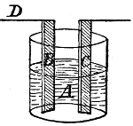
Production of electric current in chemical battery. It will first be necessary to explain how electric currents are produced by means of chemicals. In a jar A, Fig. 1, are placed two plates B and C, one zinc, and the other copper, each having connected to it at the top a copper wire of any convenient length. The plates are kept in position by means of pieces of wood, and the jar is about half filled with a solution of salt and water, or sulphuric acid and water; if then the two wires are joined, a current of electricity at once flows through them, however long they may be. Current very weak. The current produced in this manner is very weak, and does not even keep what strength it has for any length of time, but rapidly gets weaker until quite imperceptible. The[2] current is, however, continuous; that is, it flows steadily in the one direction through the wire, and may be used for ringing bells, or for other purposes where a feeble current only is required to do intermittent work. The wire E in connection with the copper plate is called the positive lead, and the other the negative, and the current is said to flow from the copper plate, through the wire E through the circuit to D, and thence to the zinc plate, and through the liquid to the copper plate. Current compared to circulation of the blood. The current has often been compared to water flowing through a pipe, but I think it can be better compared to the blood in the human body, which through the action of the heart is continually forced through the arteries and veins in one steady stream. There is, however, this difference, that there is no actual progression of matter in the electric current, it being like a ripple on water, which moves from end to end of a lake without the water itself being moved across. Now that I have given you an idea of how the current acts, I must try and explain how different degrees of strength and volume are obtained.
Strength and volume of current. In the first place, let us consider what constitute strength and volume in an electric current, or at least try and get a general notion about them. For this purpose I shall compare the electric current to water being forced through a pipe; and the strength of the electric current, or electromotive force, written for short E.M.F., will be like the pressure of[3] water at any part of the pipe. Two pipes may carry different quantities of water, and yet the pressure may be the same in each; in one a gallon of water may pass a given point in the same time that a pint passes the same point in the other, and yet in each case the different quantities may pass that point at the same speed. Thus in electricity, two currents may be of different volume or quantity, measured in ampères, and yet be of the same E.M.F. measured in volts; or they may be of different E.M.F., or pressure, or intensity, and yet be of the same volume. If any work is to be done by the water forced through a pipe, such as turning a turbine, it is evident that pressure of itself is not sufficient, seeing that a stream an inch in diameter may be at the same pressure as another a foot in diameter. So with the electric current, if work is to be done, such as driving a motor or lighting a lamp, it is not sufficient to have a certain E.M.F.; Pressure not sufficient without volume. there must be quantity or volume in proportion to the amount of work, so that if it takes a given quantity to work one lamp, it will take twice that quantity to work two lamps of the same kind. It must not be inferred from this, that if one lamp requires a certain E.M.F., that two lamps will require it to be doubled, as such is not the case, except under certain conditions which I will explain later on.
Action of current is instantaneous. The action of electricity is practically instantaneous in any length of wire, so that if the current[4] is used to ring two bells a mile apart, but connected by wires, they will commence to ring simultaneously. I have so far not said anything about resistance to the passage of the current through the wires. I shall therefore refer again to our comparison of the current to water forced through a pipe, and you will agree that a certain sized pipe will only convey a certain amount of water in a given time. If a larger quantity is to be conveyed in the same time, a greater pressure must be applied, or a larger pipe must be used.
It is evident that increasing the size of the pipe will get over the difficulty more readily than increasing the pressure of the water. The pipes themselves offer a certain resistance to the passage of the water through them, in the shape of friction; so that if an effect is to be produced at a distance, rather more pressure is required than if it is done close at hand, so as to make up for the loss sustained by friction.
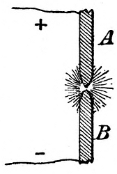
Resistance to the passage of the current. Much the same may be said of the electric current; a certain sized wire will only carry a certain current, and if more current is required, a thicker wire must be used to convey it, or it must be of a greater E.M.F. It is usually more convenient to increase the thickness of the wire than to increase the E.M.F. of the current. The wire offers a certain resistance to the passage of the current through it, which may be compared to[5] friction, and this resistance varies according to the metal of which it is composed. Copper the usual metal for conductors. Copper is the metal in ordinary use for wires for electric lighting purposes, and the purer it is the better will it convey the current. Iron is used for telegraph wires on account of cheapness, the current used being so small that this metal conveys it readily enough; if copper were used, the wires will only require to be about one-third the diameter of the iron ones. The following are the respective values for electrical conductivity of various metals when pure, taking silver as a standard:—Silver 100, copper 99·9, gold 80, zinc 29, brass 22, iron 16·8, tin 13·1, lead 8·3, mercury 1·6.
Heat produced by current when wire is too small. If a wire is made to convey a current which is too large for its electrical capacity, it will get heated, which decreases its conductivity, with the result that the heat increases until finally the wire fuses. I shall have more to say about this when speaking of electric lighting.
I have shown how the electric current is produced by the action of chemical or primary batteries, and how this current will flow through suitable conductors.[6] Current produced by mechanical means. I shall now explain how mechanical power may be converted into electricity. It has been found that if a wire, preferably of copper, of which the ends are joined together, is moved past a magnet a current is induced in the wire, flowing in one direction while the wire is approaching the magnet, and in the opposite direction while it is receding from it. Alternating current. This is then not a continuous current like we obtained from the chemical battery, but an alternating one, and you will see later on how it can be made to produce similar effects. The oftener the wire passes the magnet the more electricity is generated, so that if we make a coil of the wire and move a large number of parts of wire past at one time, the effects on each part are accumulated; and if instead of having one magnet to pass before, we have several, the effects will be doubled or trebled, &c., in proportion to the number. If, again, the coil is moved at an increased speed past the magnets, the effects will be still further increased.
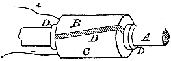
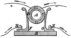
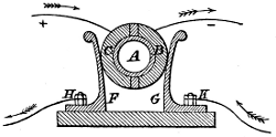
Magneto-electric machines. The knowledge of these facts led to the construction of the various magneto-electric machines, of which a familiar type is seen in those small ones used for medical purposes. They contain a large horse-shoe magnet, close to the end of which two bobbins of copper wire are made to revolve at a high speed, and all who have used these machines know that the more quickly they turn the handle the greater shock the person receives who is being[7] operated upon. Shock produced by interruption of current. The current generated is really very feeble, the shock being produced by interrupting it at every half revolution by means of a small spring or other suitable mechanism. If the current is not so interrupted, it cannot be felt at all, which may be proved by lifting up the spring on the spindle of the ordinary kind. The current is an alternating one, and changes its direction throughout the circuit, however extended it may be, at every half revolution. The current must be commutated. If it is required to have a continuous current, use must be made of what is termed a commutator, and I shall endeavour to explain the manner in which it acts as simply as possible. Without going into any further details as to the construction of the bobbins, and their action at any particular moment, I shall content myself with saying that if the wire on the two bobbins is continuous, and the ends are connected, the current will flow one way during half a revolution, and the other way during the other half. Description of commutator. [8]Now, in Fig. 2, on the spindle A on which the bobbins are fixed, is fitted a split collar formed of two halves B and C, to which are joined respectively the ends of the wires + and -. This collar is insulated from the spindle by a suitable insulating material, that is to say, a material which does not conduct electricity, such as wood, ivory, &c., and is represented in Fig. 2 by the dark parts D. So far the circuit is not complete, so that however quickly you turn the machine no current is produced. If, however, some means is employed for joining B and C by a conductor, the alternating current is produced as before. In Fig. 3, I show a section through B A C. On a base E made of wood, are fixed two metal springs F and G, which are made to press against B and C respectively; wires are connected at H and K, which, joined together, complete the circuit. A continuous current is said to be + or positive where it leaves a battery, and - or negative where it returns; it will be convenient to use these signs and terms in the following explanation. Current though alternating in the dynamo, is continuous in the circuit. At one portion of the revolution the spindle will be in the position shown in Fig. 3, and the + current is flowing into B, through F, to the terminal H, thence through the circuit to the terminal K,[9] through G to C, and so back through the - wire to the bobbins of the machine. In Fig. 4 the spindle has made a half revolution, bringing B in contact with G, and C with F. But by this half turn the current is reversed in the bobbins, and the + current flows into C, through F, to terminal H as before, and through the circuit to K, through G and B, back to the bobbins. Continuous current used for electro-plating. Thus you see that in the circuit the current will be always in the same direction, or continuous, although in the bobbins it is alternating, and may be used for any purpose for which a continuous current is required, such as electro-plating, &c.
There are various forms of the magneto-electric machines, as well as of commutators, but the foregoing shows the general principle of them all.
It will now be necessary to explain the nature of a dynamo-electric machine, called, for shortness, a[10] dynamo, and to show in what it differs from a magneto-electric machine.
I have explained how an electric current is produced by a wire passing in front of a magnet; now, this magnet may either be of the ordinary kind, or it may be what is termed an electro-magnet. Current will magnetise an iron or steel bar. One of the effects which electricity can be made to produce is the magnetising of steel bars to form the ordinary and well-known permanent magnets which are used in ships’ compasses, &c. To produce this effect, part of the wire in a circuit is made into a spiral as in Fig. 5.
Permanent magnet. The steel rod to be magnetised is placed within the spiral, and a continuous current of electricity is then sent through the wire, which causes the rod to become magnetised with a North pole at one end, and a South pole at the other. The more current is passed through the circuit, and the more turns are in the spiral, the more quickly and strongly is the rod magnetised; and it will retain its magnetism for an indefinite time if made of suitable steel. There is a point at which the metal is said to be saturated with magnetism, and the strength it has then acquired will be that which it will retain afterwards, although while under the influence of the current that strength may be considerably exceeded. Electro-magnet. If instead of a steel[11] rod one of iron is placed in the spiral, and the current is passed through as before, it will be magnetised in the same manner; but as soon as the current is stopped, the rod loses almost all its magnetism, and if the current is then passed in the opposite direction the rod will be magnetised in the opposite way. The softer and more homogeneous is the iron, the more instantaneously will it acquire and lose its magnetism, and the greater strength of magnetism it is able to acquire. An iron bar, round which are wound a large number of turns of insulated or covered wire, constitutes an electro-magnet. Where the magneto and dynamo machines differ. The difference then between a magneto-electric and a dynamo-electric machine is, that in the former permanent magnets are used, and in the latter electro-magnets take their place. I do not intend to go into particulars as to the construction of the various dynamos in present use, as there are many books to be had in which these machines are fully described. I need merely say that in the so-called continuous-current dynamos, the whole or part of the current produced is made to pass through the coils of the electro-magnets, thus inducing in them the required magnetism. I showed how, in the magneto-electric machine, the currents are collected by means of a commutator, and it is evident that in Figs. 2, 3, and 4 there might be separate wires coming from each bobbin to B and C; and if there were more than two bobbins, there might still be[12] two wires from each to B and C. On the other hand the collecting collar might be split into more sections; in fact there might be as many sections as bobbins. To show how the current is collected in continuous-current dynamos, I must give a short explanation of the revolving part or armature of a standard type of machine.
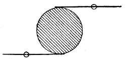
Armature of so-called continuous-current dynamo. In Fig. 6 is shown a horse-shoe magnet, with its North and South poles, N and S. Between these poles is made to revolve the armature, composed of a number of coils of wire made to form a ring like a life-buoy. The ends of the wires are made to lie along a collar on the spindle, made of some insulating material, each wire being parallel to its neighbour, and kept separate from it, as shown in Fig. 7.
Type of commutator. These wires are so arranged that if one end of a sectional coil is on top of the spindle at a given moment, the other will be on the under side. If[13] then, as shown in Fig. 7, a rubber of copper, made in the form of a brush of copper wire for convenience, is placed in contact with the upper Commutator brushes. part of the commutator collar, and another similar one with the lower, it is evident the circuit will be completed in the same manner as before explained.
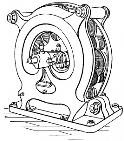
Current continuous in the circuit. A wire which is + when above the spindle, will be - when below it, and as the spindle revolves the current changes in the various wires from - to +[14] as they reach the top, so that it will always therefore be + in the upper brush and - in the lower one, and will accordingly be continuous through the circuit. It will be seen in the illustrations of various continuous-current dynamos, that though their shape and arrangement differ, the mode of collecting the current is much about the same as I have described above. Figs. 8 and 9 show some of the continuous-current dynamos at present in use.
Alternating-current dynamos. I will now explain the nature of an alternating-current dynamo.
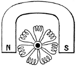
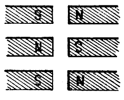
The principal difference between the continuous-and alternating-current dynamo, is in the number of magnets used. Most of the former have only four magnets, while the latter have frequently as many as thirty-two. Current not commutated. In reality, as I have shown, these are all alternating-current dynamos, only that in the so-called continuous-current ones, the current is[15] commutated, whereas in the others it is not, but is used as it is produced. In the principal alternating-current dynamos, a number of small magnets, usually sixteen, are attached to a framework directly opposite a similar number of others of the same size, the space between the ends being only about an inch or two. These are all electro-magnets, and are wound in such manner that when excited by a current, every alternate one shall have the same magnetism, as in Fig. 10, and every opposite one a contrary magnetism.
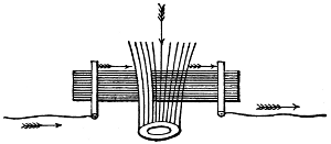
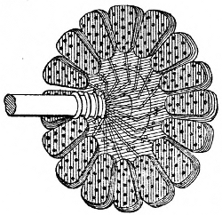
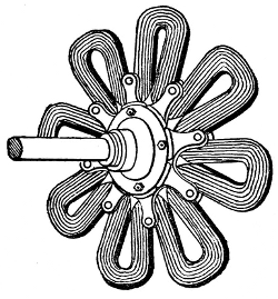
Intense magnetic field produced. This produces an intense magnetic field between the ends of the magnets, and in this space revolves the armature. This armature, in the Siemens dynamo, is composed of a disc having as many bobbins on the periphery as there are magnets on each side of the dynamo. As each bobbin approaches each magnet a current is induced in one direction, which is reversed when the bobbin recedes; thus an alternating current is produced, which is collected by connecting the ends to insulated rings or collars on the spindle, and having small copper brushes or rubbers in contact with them. Simplicity of Ferranti armature. In the Ferranti dynamo, the armature is quite different, and much more simple, as comparison of Figs. 11 and 12 will show.
It consists of a copper tape bent in and out so as to form a sort of star with eight arms, the number of[16] layers of insulated copper tape being from ten to thirty, according to requirements. The centre is made in a similar shape with bolts or rivets holding each convolution in place. The two ends of the tape are attached respectively to two collector-rings on the spindle, against which press two solid metal rubbers which carry off the current for use in the circuit. It can be shown that as each arm approaches a magnet a current will be induced in one direction, which will be reversed as each arm recedes; and therefore an alternating current will be produced. Large number of alternations of the current. As there are sixteen magnets for the armature to pass at each revolution, there must be sixteen alternations of the current during the same time, so that if the speed of the armature is 500 revolutions per minute, there will be 500 × 16 = 8000 alternations in one minute. These alternations being so extremely[17] rapid, when this current is used for electric lighting, the steadiness of the light will be in no way affected, but will remain as constant as with a continuous current.
Alternating current cannot be used to excite an electro-magnet. The alternating current produced by these dynamos cannot be used for exciting an electro-magnet, as the magnetism would be reversed at every alternation; a separate small dynamo of the continuous type is therefore used as an exciter to magnetise all the electro-magnets in the field, and it is usually coupled on to the same spindle, and therefore goes at the same Exciter coupled on to same spindle as dynamo. speed as the alternating-current dynamo. The exciter is usually of a size to be able to do alone[18] about one-tenth to one-twentieth of the work that the larger machines does in the way of lighting; so that if from any cause the latter is disabled while the ship lighted by it is at sea, the exciter may be used alone to do a portion of Power of exciter if used alone. the lighting, in the first-class saloon for instance. This can only be done if the exciter is so constructed as to give the proper E.M.F. that the lamps require.
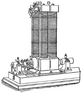
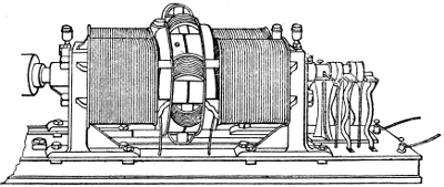
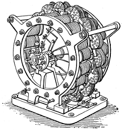
Figs. 13 and 14 are illustrations of two of the alternating current dynamos in use on board ship and elsewhere.
Production of electric light. I have explained how power can be converted into electric currents, either continuous or alternating, and I must now show how these currents can be applied to the production of light.
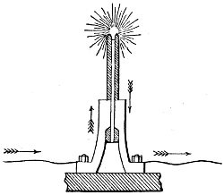
Arc lights. The current may be used to produce an arc light in the following manner:—Two carbon rods, A and B, are held by suitable means in the position shown in Fig. 15, and the two wires from a dynamo are joined respectively to A and B, the upper one always being the positive lead when a continuous current is used. When the current is sent through the circuit, it passes through the carbons A and B, which are conductors. Immediately this occurs, suitable mechanism in the lamp, being acted on by the current, or by hand in the case of search-lights, or by clock-work, moves the two carbons a small distance apart, with the consequence that a dazzling arc of light is formed between them. Mechanism to regulate carbons. If the carbons get too far apart, the mechanism brings them nearer together again, and on the delicacy with which it acts, depends the steadiness of the light. It would be useless to explain how this mechanism acts, as it is in a different form in each maker’s lamp. Some lamps suitable for alternating current. Some lamps have been constructed for use with an alternating current, but with the majority a continuous current is used.[20] While an arc light is burning the carbons waste away, the upper one more rapidly than the lower, and the mechanism has to approach them constantly to make up for this waste.
When carbons are consumed light goes out. When the carbons are consumed as far as convenient, an automatic arrangement cuts off the current, and the light goes out; or it diverts the current to another set of carbons, which at once light up. The carbons are made in suitable lengths to last a certain number of hours, four, six, eight, &c. In Fig. 16 is shown an arc lamp complete.
Arc lamp very complicated. An arc lamp is of necessity a complicated affair, which it is not advisable to have on board ship, except where an electrician is engaged permanently.
Jablochkoff candle. Another way of producing light is to use the current in what is called an electric candle, of which a familiar type is the Jablochkoff candle.
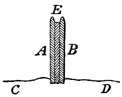
Fig. 17 shows the form of this candle, A and B being two carbon rods parallel to one another, and joined, but at the same time insulated from one another[21] by kaolin, a sort of chalky substance, which is a non-conductor.
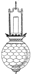
The wires C and D from the dynamo are joined respectively to A and B through metallic supports, as in an arc lamp, and when the current is turned on it flows through C A and across by a small strip of carbon E to B and D back to the dynamo. Arc formed between the carbons. The strip E is only large enough to carry the current across for a moment, and is immediately consumed, but an arc of light is then formed between the carbons as in the arc lamp. As the carbons consume, the kaolin in between burns away, just in the same manner as, in an ordinary candle, the wick is consumed and the wax melts and burns away, except that in the latter case the wax feeds the light, whereas the kaolin is only used to keep the carbons the required distance apart and the arc of light from running down them.Candles require alternating current. It is evident that the carbons must be consumed equally, for which reason use must be made of the alternating current. Any unsteadiness that occurs in the light produced is consequent on unsteadiness of the current, or impurities in the carbons, &c., there being no mechanism of any kind required. These candles do not give such a great light as arc lights, but it is of the same nature in every way. Fig. 18 shows one of these candles in its holder, from which can be[22] seen how electrical contact is made with the two carbons.
If the current is interrupted in any way, and the light goes out, it will not be produced again automatically, but requires a small piece of carbon between the two carbons as a path for the current to pass across as in the beginning.
Incandescent lamps. A third form of electric light is produced by using the current in an incandescent lamp.
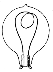
To explain the action of an incandescent lamp, I must refer back to what I said about wires getting heated by a current being passed through them which was too large for their capacity. If two large wires are joined by a small one, and a strong current is passed through the circuit, the small wire rapidly gets red hot, and finally fuses. Vacuum formed in lamp prevents combustion If this small wire is contained in a globe from which the air is exhausted, when the current is passed through it, it gets red,[23] then white hot, and when very brilliant gets fused. If, instead of wire, we have in the small globe a thin filament of carbon, when the current is passed through, we get a brilliant light which remains constant because the carbon does not fuse, and it cannot burn away for want of air. Fig. 19 shows a Swan lamp, and Fig. 20 an Edison lamp, both made on this principle.
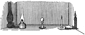
Vacuum not perfect. If in these lamps the vacuum were perfect, the carbon filament would never get consumed; it is, however, impossible to get a perfect vacuum, but the better it is, the longer will the filament last. Incandescent lamps are the only ones that are suitable for house or ship lighting. Advantages of incandescent lamps for house and ship lighting. They give a yellowish light like a good gas-flame, they do not consume the air of a room, they cause no smell, and only give out a very slight heat. They are perfectly safe, because if the globe gets broken and allows air to get in, the filament is instantly consumed, and the light goes out. They can be put in all sorts of places where it would be impossible to[24] have any other lamps, such as near the ceiling, close to curtains, in a room full of explosives or combustibles, and even under water. Unaffected by wind, and suitable for either continuous or alternating currents. They are not affected by wind; they can therefore be used under punkahs, or near open windows, sky-lights, or ports, or in the open air. These lamps can be used with either continuous or alternating currents, but will probably last longer with the latter, because, when a continuous current is used, particles of the carbon of the filament appear to be conveyed from one end of the filament to the other, reducing the thickness at the one end, until finally it breaks. This evidently cannot occur with an alternating current, as the impulse in one direction is counteracted by the following one in the opposite direction. If the current used is of too high a tension for the lamps, they will show an intensely brilliant light for a short time, but the filament will soon be destroyed, and the lamp rendered useless.
We have now to consider the means used for conveying the current, continuous or alternating, to the lamps we intend to use. Leads made usually of copper wire. The leads for the electric current, which correspond in some measure with the pipes which convey gas, are made of copper wire, as pure as can be obtained, covered with some insulating material to prevent the escape of the current through contact with other conductors. The[25] size of the wire is regulated according to the amount of current which is to be conveyed; it will do no harm to have it of twice the required section, but if it is of less than the required section, it will offer so much resistance to the passage of the current, that it will probably get fused in a very short time. Short circuit. If the lead attached to one terminal of the dynamo comes back to the other terminal without there being any lamps in the circuit, or other means of making use of the current, it is said to be short circuited, and if the dynamo is kept going something must give out very soon. The two leads must therefore never be connected with one another, except by a lamp or other resistance, and the manner in which the lamps are placed, and the size of the leads, depend upon the relative tension and quantity of current and the kind of lamps to be used. High E.M.F. for arc lights, but low for incandescent. If the current is to be used in arc lamps it is usual to have a high E.M.F., which allows of the leads being of small section; but if it is to be used in incandescent lamps it is found more convenient to have a low E.M.F., and as this implies a large quantity of current, the leads have to be of large section.
Arc lights in series. Arc lamps usually require to be placed in series, that is to say, in such a manner that the current, after leaving the dynamo, passes through each lamp in succession. The E.M.F. required in this case is the sum of the E.M.F. for each lamp, the quantity required being the same as for one lamp. This[26] accounts for the high E.M.F. used in arc lighting and the small size of the wire for conducting the current. Incandescent lamps in parallel circuit. Incandescent lamps can be either in series or parallel, and frequently the two systems are combined. To explain the meaning of having lamps parallel, we will suppose the two leads from a dynamo to be taken along a wall, parallel to one another, and about six inches apart, ending at the end of the wall, but not connected in any way. If we then place lamps at intervals between the two leads, connecting one loop of each to the upper lead, and the other to the lower lead, by means of small copper wire, these lamps are said to be all parallel. E.M.F. same for one lamp as for a number. In this arrangement the current required is the sum of the quantity necessary for each lamp, but the E.M.F. is the same as that required for one lamp of the same kind. As we therefore require to send a large quantity of current through the leads at a small pressure or E.M.F., these leads must be of large section. In the above arrangement each lamp may be turned on or off separately without affecting the others. Sometimes two or more lamps are placed in groups between the parallel leads; these are then in series with regard to one another, and can only be turned on or off two or more at a time, in other words, one group at a time. If lamps suitable, each one turns on and off separately. If our dynamo is producing a current of 100 volts E.M.F. when working at its proper speed, and our lamps are 100-volt lamps, we shall be able to turn each lamp[27] on or off separately; but if we want to put in 50-volt lamps, we must place two together, and we shall then have to turn them on or off two at a time. I am supposing that in both cases the lamps require the same quantity of current, though of different E.M.F.
Safety fuses. To prevent the lamps being spoilt by the current being too strong through a sudden increase in the speed of the dynamo, as also to prevent the leads getting fused, and perhaps setting fire to the casing, it is usual to have safety fuses in various parts of the circuit. These are of different kinds, but a typical one consists of a small lead wire, large enough to carry the normal current, but which fuses when the current is too strong, and at once interrupts its passage. The lamps in the same portion of the circuit are then extinguished and so saved from destruction, and cannot then be lighted again until the fuse is renewed, which, however, can be done with ease.
We will consider now the case of a steamship to be lighted by means of incandescent lamps. It is sometimes a matter of some difficulty to fix on a suitable position for the dynamo and engine, especially in ships which have already been running for some time. Position for dynamo. In selecting a position, it must be borne in mind[28] that a dynamo will work best in a cool clean place, cleanliness being most important. If a lot of coal dust is flying about where the dynamo is working, it will be drawn into it, and tend to impair its electrical, as well as mechanical efficiency. Dynamo to be kept clean and cool. If the dynamo is kept properly lubricated, it will work well enough in a hot place, but we must remember that the heating of the wire which makes up a large portion of the dynamo, reduces its conductivity, so that the cooler it is kept the better. The dynamo should be so placed that the engineer can get to every side of it easily. Quick-speed engines. If a quick-speed engine is to be used for driving it direct, it will make a very compact installation, but there seems to be some difficulty as yet in getting suitable reliable engines, besides which many marine engineers object to quick-speed engines altogether. Slow-speed engines with belts. If a slow-speed engine is to be used, a belt is of course required to get the necessary speed on the dynamo, and various precautions are needful to prevent the belt slipping off the pulley when the ship is rolling about in a sea-way. In all cases, the engine and dynamo should be placed with their spindles fore-and-aft, or in a line with the ship’s keel, the rolling being felt more than the pitching. Means of keeping belt on the pulley. There are various ways of keeping the belt from slipping off the pulley. Some have flanges on the pulley, others have guides or rollers on each side of the belt, each plan having its advantages and disadvantages; but some plan must be[29] used, otherwise the belt slips off, usually in the middle of the first-saloon dinner, and out go all the lights, besides which the belt may be considerably damaged before the engine can be stopped. Engine must work steadily. The engine must be one that will work very steadily, otherwise the lights will pulsate at each revolution of the engine, which is most unpleasant. If the engine is a single one, it must have a large fly-wheel, or a driving-wheel large and heavy enough to answer the same purpose. A good sensitive governor wanted. The engine requires a good sensitive governor, so as to keep the speed regular when some of the lamps are turned on or off. When the engine and dynamo are in the main engine-room, the throttle-valve, or a stop-valve, should be in a convenient place for the engineer on watch to get at so as to instantly shut off the steam if the belt slips off or breaks. In ships where an electrician is carried there will not be the same necessity for this precaution. The belt must be kept tight. It is necessary to have some means of tightening up the belt, so as to keep it from slipping round the pulley. Where the engine and dynamo are on the same level there may be a screw arrangement in the base-plate of the latter by which the distance between centres can be increased. Where the engine and dynamo are on different levels, and the latter is a fixture, recourse must be had to a roller, bearing against the upper part of the belt and capable of screw adjustment. If link leather belting is used, it will be found[30] necessary to take out several rows of links each day until it has finished stretching. A handy belt stretcher. A very handy thing to use for this purpose, and which can be made on board by an engineer, is a double clamp with a screw in between, just like the ones which are being sold for stretching trousers which have got baggy at the knees. Whatever belt is used, it is very important that there should be no joint or inequality which can cause a jump or slip when going over the pulley, as this will cause the lights to pulsate each time. Friction gearing. In America friction gearing has been tried, but I do not know with what success. From my experience of friction gearing, I am inclined to think it might do very well. There is certainly no doubt that direct-acting quick-speed engines are the ones to use, and it is only a question of getting a suitable one.
Switch-board near dynamo. The dynamo being firmly fixed in position, the main leads are connected to it, and carried along to the switch-board, which should be in a convenient position near at hand. On this switch-board are usually placed the large safety fuses. The board should have a cover to it, to prevent any one meddling with it, and to keep it clean. The main leads are of a large size, and from these other smaller ones branch off, being spliced and soldered to them. Leads of different colours. It is a very good practice to use leads of two different colours, as we can then work by the following rule: Never connect together two leads of different colours except by means of a lamp or other[31] resistance. The size of the various leads depends on the current to be conveyed, and is a matter for the electricians. Main leads and branch leads. On the main-deck of a large passenger steamer, the main leads may be carried along side by side under the upper deck, and from these, smaller ones branch off into the various sets of rooms, smaller ones still going into each room. In each room there will be one lamp with its switch to turn it on or off as desired, and a safety fuse. Lamps held in frosted globes. The lamps are held in small brackets, and are contained when desired in frosted globes, which diffuse the light and make it very pleasant. When these globes are held rigidly in the brackets, the least knock breaks them. A very good bracket I have seen in use is one which allows the globe to move about on its support when touched, being at the same time sufficiently a fixture to resist the motion of the ship; and in the particular ship in which I saw these used in the first saloon, there was not a single breakage during a four months’ voyage. Switches for each lamp. The switches for turning each light on or off can be under the control of the passengers, or, on the other hand, they can be fitted to work with keys kept by the stewards, as thought most desirable.
Lamps of various candle-powers. The lamps used can be of various candle-powers, within certain limits, and of whatever make is considered best. They can also be of various makes, as long as they are constructed to stand the same E.M.F. The lamps in the passenger berths give[32] quite sufficient light if of 10-candle power; the ones for lighting the saloons, passages, and other large spaces, may with advantage be of 20-candle power. In these days of luxurious travelling, when the various lines are trying to attract passengers to their particular ships, what follows may be thought worth consideration. In steamers going through the tropics to India, China, Australia, &c., it is usual to get up dances, concerts, and other entertainments on the quarter-deck, at times when it would be impossible to do anything below on account of the heat. Plan for lighting quarter-deck at times. The quarter-deck then has to be lighted up. This is effected by means of globe oil-lamps hung about here and there, two being hung in front of the piano, in unpleasant proximity to the head of the obliging lady pianist. Now in a ship lighted by electricity, there is no reason why a couple of leads should not be brought up from below through a skylight or other opening, on to the quarter-deck. Arrangement of temporary leads. Indeed the leads might be arranged to screw into a place in the deck, or on the side of a skylight, just in the same manner as a hose is connected for washing decks. These leads would have holders for lamps fitted permanently at intervals, and when required for use would be stopped up along the awning-spar or ridge-chains, and the lamps screwed or hooked into the holders. With a few handy men, five or ten minutes would suffice to arrange the whole thing after the leads had once been fitted. Leads and lamps always ready, and easily fixed up. The leads once fitted[33] for this purpose would be always ready for use, and could be kept coiled away in a box which might also have a compartment to contain the dozen or so of lamps required.
If the dynamo is already running as many lamps as it is capable of, some of the bedroom lights may be turned off while the quarter-deck is being lighted. Another thing which I think has not yet been done is the following. Lighting of ships’ holds. When working cargo at night, and indeed during the day to some extent, lights are of necessity used in the holds. Danger of fire with oil lamps. The theory is, that no naked lights shall be allowed, but the practice is this: lamps are taken below, get knocked about, the wicks fall down and want pricking up, the lamps are opened for this purpose, and as they are found to give more light without a dusty glass round them than with it, they are left open. Candles are often taken below lighted, and even matches struck to see the mark on a bale. I am aware that arc lamps are used in the Royal Albert Docks, London, in connection with the dock lighting, lamps being carried below when required, with flexible leads attached, and that, in some few steamers, arc lamps have been used in the same manner in connection with their own plant. Arc lamps not suitable. These arc lamps are, I think, not nearly as suitable as incandescent lamps for the purpose of lighting up a ship’s hold; the light is too glaring, and casts deep shadows amongst the bales and cases, besides which, the lamps are large and clumsy. Arrangement of leads for incandescent lamps. I[34] would suggest that leads should be carried behind the stringer-battens in the ship’s side, or along under the next upper-deck, having simple sockets or holders for incandescent lamps at certain intervals. Whoever might be in charge of the hold would screw or hook on the lamps as required, and so light up every part of the hold thoroughly while work was going on. Work carried on better, and pilfering of cargo prevented. There would be no risk of fire, and I am convinced that the extra leads and lamps would pay for themselves in a very short time, because work would get on more quickly, and pilfering of the cargo would be in a great measure put a stop to. Hold leads disconnected while at sea. The leads for the holds could be so arranged as to be quite unconnected with the dynamo while at sea, so that there could not be the remotest possibility of the current finding its way below when not wanted. In fine, there is no reason whatever why a ship’s hold should not be lighted up when required, as well as a warehouse or store on shore.
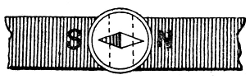
Installation complete. Now, we will suppose that our installation is complete, ready for working, everything having been pronounced in order by the electrician who has looked after the work. Lights wanted as night approaches. Evening is approaching, and the lights will soon be required; we must therefore see that our engine and dynamo are ready for a start. Precautions before starting dynamo. If the engine and dynamo are separate, the belt must be felt, to see that it is tight enough, otherwise it must be tightened by whatever means are provided for the purpose. Lubrication must be perfect. We must also see[35] that the engine and dynamo are properly oiled, and that the worsteds are down the tubes of the oil-cups, and working properly, not dry, as I have known them to be, with fatal results to the dynamo. Commutators and collectors require very little oil. If the lubrication is performed by means of tubes leading to each bearing from an elevated oil-box, we must see that the oil really gets to the bearings, and regulate its flow as required. The commutators and collector-rings and rubbers require only a wipe of oil, just sufficient to prevent undue wearing of the surfaces; if too much is put on them, they will spark a great deal, and sparking will wear them away more quickly than friction. Position of brushes. The brushes of copper wire which collect the current of the exciter dynamo, and others of similar pattern, must be placed so that the ends press on the commutator as shown in Fig. 21. The ends should project just a little way beyond the point or line of contact, and when the dynamo is running, there should be very little sparking. I am supposing that our plant consists of an alternating-current dynamo with a small exciter. The wires leading from the exciter to the other dynamo remain always connected, as there is no need for meddling with them.
[36] Start the engine. We will now start the engine, and thereby set the dynamo going round, slowly at first, and gradually up to the speed required. The main switches are not yet turned on, so there is no current going through the leads as yet; what then is being done? Switches not turned on. A current is being produced by the exciter only, and is magnetising the electro-magnets of the larger dynamo, No current except from exciter. and if we want to know if it is really doing its work as intended, we just hold a small pocket-compass over the ends of two opposite magnets of the dynamo, and observe how the needle points. Testing work of exciter. It should at once take up the position shown in Fig. 22, and if then held over the next couple in like manner, the needle should simply turn round, and point in exactly the opposite direction. If it points in any other direction, there is something wrong with the connections. If, however, the connections are right at starting, they will of course remain right, and there should be no need for this test. Dynamos very powerful magnets. It is well to remember that when dynamos are working, they are, or contain for the time being, very powerful magnets, therefore if we bend over them to examine them, Look out for your watches! our watches will get magnetised, which does not improve their qualities as time-keepers. Say that our dynamo is now going round at the required speed, which may be 500 or 600 revolutions per minute; the engine is not using much steam as yet, because very little work is being done. Switch on the lamps. We now switch on a set of[37] lamps; this closes the circuit, and the large dynamo begins to produce its alternating current, which goes through the lamps and lights them up. Current is produced in large dynamo. This, however, gives the engine more work to do, and more steam must be turned on, otherwise the necessary speed will not be kept up. We switch on all the other lamps as required, and must see that the speed of the dynamo is kept constant. Difference of a few lamps compensated by governor. A difference of a few lamps, affecting the engine to a small extent only, should be compensated automatically by the governor. If the brightest lamps are not bright enough, the speed should be increased a little, but care must be taken not to overdo it, because if the current is too strong, some of the safety fuses will melt, and the corresponding lamps will go out. It must not be inferred from what I have said, that it is necessary to run the dynamo at first without switching on any lamps. Turn all lamps on, and light up gradually. On the contrary, a better effect will be produced if all the lamps are switched on before starting, as they will then gradually work up to their full brilliancy; whereas, if one set of lamps is started first, and run bright, and we then switch on another set, the current at first will be too small for the two sets, and the first set will get quite dull, remaining so until the dynamo is going at its proper speed again. Inequality of light in different lamps. When lighted up for the first time, it will be found that some of the lamps are much brighter than others; this is because the lamps at present made[38] are not of perfectly equal resistances. We must go round, then, and note where the dull ones are, and we can either at once, or during next day, shift them into the bathrooms and places where such a perfect light is not required. All the lamps in one room, the first saloon, or music room, for instance, should be equalised as much as possible, and in such places the brightest should be used. Nothing looks worse than to see a couple of dull lights in the same room as a lot of bright ones. By seeing to these matters we can make the lighting much more satisfactory than it otherwise would be. During the first few evenings we shall probably have some of the lamps go out through the filaments breaking. Weeding out of bad lamps. This I consider a weeding out of defective lamps, because if it were that the current was too strong, the fuses would have given way. Some of the fuses give way when the current is not too strong; this is owing to imperfections in the fuses, and they must be replaced by spare ones. Lamps not to be run too bright. For the sake of economy, it is well not to run the lamps too bright. Without giving the lamps the maximum current a very good light can be obtained, and they will last all the longer. I need hardly say that there is a medium in this as in everything else, and it does not look well when a candle is placed alongside of an electric lamp to enable a person to read or write in comfort.
All this time the dynamo is running, and we must feel the bearings occasionally to see if they[39] are keeping cool. No trouble with dynamo if oiling is attended to. There will be no trouble if the lubrication is all right. If the oil does not get into the bearings as it should do, they will heat, jam the spindle, or seize, and bring up the engine or break the belt. The lights will then all go out, and everybody will say hard things of the electric light, while the fault really rests with us. Seizing. Sometimes seizing occurs through the spindle not being slack enough in the bearings, but this generally occurs while testing the dynamo at the works.
Oil must be thin. It must be borne in mind that in dynamos the spindle must be a good fit, and there may be room in the bearings for ordinary engine-oil while there may not be for a thicker oil, such as castor oil. Therefore, if the bearings show a tendency to heat, it may improve matters to thin the oil used with petroleum. While giving the dynamo its proper supply of oil, we must only apply it in the proper places. If we let the bobbins get smothered in oil, the insulating material on the wire will get rotted, and a short circuiting will probably take place. The dynamo must be kept clean. The dynamo cannot be kept too clean, and there should be a canvas cover to put over it while not in use, especially while coaling. We will suppose that all is going on right; a steward comes along and says: Little troubles with the lamps. “Mr. So-and-so, I cannot get the lamp in number 6 berth to light although I have turned the switch the right way.” “All right, I will go and look at it,” you answer. Now, let us see what is the matter. We unhook or[40] unscrew the lamp, and look at the filament; it is not broken. We replace the lamp again, and are careful that it makes good contact; but still no light. No safety fuse. Let us look at the safety fuse; why, there is none! it has been missed out. We get one of the spare ones out of our electric store, and put it in its place, and the lamp lights properly at once. We find another lamp out, and look at it. We see at once that the filament is broken, so there is no question about this one; it must be changed. Hallo! what is up with this one? it goes in and out all the time like a flash light. The current must be getting to it all right, otherwise it would not light at all. I see what it is; it is a Swan lamp, and the spring is not pressing quite fairly on it, so that one hook is making good contact, Effect of vibration of ship on lamps. while the other tightens and slacks with the vibration of the ship. This is soon set right by turning the spring round a little, or hooking the lamp the other way. What to look to if a lamp is out. Or it is an Edison lamp, which has got slightly unscrewed, and no longer makes good contact at the back end of the holder. In some lamp-fittings the ends of the leads are held in a spring grip in the base of the bracket, and it may happen that they have slipped out, and so broken the circuit, and extinguished the light. In the Swan lamps, and others of a similar pattern, one of the little platinum loops in the base of the lamps sometimes gets broken off; the lamp is then of no further use. Recapitulation. To recapitulate, if a lamp goes out, the first thing is to see if the[41] filament is broken, next if it makes good contact. If it does not then light up, see if there is any current getting to it; this may be found out by touching the two hooks in a Swan holder, or the back and side of an Edison screw holder, with a moistened finger. A current of 50 volts is hardly felt. With a current of 50 volts a slight tickling sensation will be felt if the current is passing through. If this cannot be felt, there must be some part or other disconnected, perhaps the safety fuse has given out, or the ends of the leads got adrift from the bracket. If in any doubt about the lamp, try another in the same place.
Incandescent lights for side lights. In some steamers incandescent lamps are used in the side lamps; they can easily be fitted for this purpose, especially when the ship is provided with lighthouses built in, as in the Anchor Line steamers. Two or more incandescent lamps can be arranged on a small stand, which will slide into the lantern, taking the place of the regulation oil lamp, and connected by flexible leads to the other leads. It would be easy to put six 20-candle power lamps in a group in each lantern, as it does not matter in what position they are placed; two might be used on ordinary occasions, while on a foggy night, the whole six could be switched on. If one lamp went out through the filament giving way, it would not affect the others, so that there would still be a light in the lantern. If, through some breakdown of the engine or dynamo, the electric current were no longer to be had, then it[42] Mast-head light. would only be necessary to withdraw the stand of lamps, and put in the ordinary regulation oil-lamp. The mast-head lamp could also be fitted with the electric light, as indeed has already been done. Arc light should never be used. On no account, however, should an arc light be used, as besides being too dazzling, it is much too uncertain; in fact many other reasons could be given for rejecting it. It is even a question whether it is an advantage to have incandescent lamps for a mast-head light. There is certainly the great advantage of not having to pull the lamp up and down to trim it, a rather risky performance in heavy weather, and also of the light not being affected by any wind that may get into the lamp; though as regards the first, English officers would never be satisfied to see a lamp dangling on the stay all day long, as appears to be the custom in some foreign steamers, besides which it would have to be lowered to be cleaned outside.
Present mast-head lights quite powerful enough. The present mast-head lights are quite powerful enough already, too much so when compared with the side lights. I am not aware of any collisions having occurred through a mast-head light not being seen in time, but how many from the side lights not being seen! It was no doubt contemplated, as indeed the regulations show, that no lights should be visible about a vessel, except the regulation lights; On passenger steamers, side one blaze of light, and side lights barely visible. but many who have seen a large passenger steamer go past will have noticed how her side was—one,[43] two, or three rows of dazzling bright lights, and will have looked almost in vain for the green or red light dimly visible in the midst of all the bright ones. If bright electric lights, therefore, are shining through the ports, we must have our side lights at least as bright, so as to give them a chance of being seen. If electric lamps are used as side lights, the dynamo must be kept running all night. If it is thought desirable to put out all unnecessary lights at 11 p.m., the leads can be so arranged that these lights can be all on one or more circuits, and the necessary ones on another.
Speed of dynamo constant, but steam power used in proportion to number of lamps in use. Although the dynamo will have to go at nearly the same speed throughout the night, it will not have the same amount of work to do, and the engine will therefore use much less steam, the consumption being in proportion to the number of lights used. An economical engineer will therefore see that bedroom lamps are not kept lighted all the evening without any necessity. On shore we should never think of keeping gas-lights blazing away for no purpose, and why should we use electricity with more lavishness, especially when it is so easy to turn a light on or off. The switches might with advantage be painted with Balmain’s luminous paint, and there would then be no trouble in finding them in the dark. No danger to life from electric current on board ship. It is well to know that on board ship, probably in all cases of electric lighting, there is no danger to life to be apprehended from touching any[44] of the leads where bare, or indeed any part of the dynamos, as the E.M.F. is usually not more than 50 volts. It is best, however, not to try any experiments, and it is a good general rule, not to touch a bare part of a dynamo or lead with both hands at the same time. The fear of getting hurt has the good effect of keeping passengers and others from meddling with their lamps.
Binnacle lamps. Electric light not suitable. I have said nothing about the use of electric lights in binnacles, though it would be a great advantage to be able to supply them with a good steady light quite unaffected by wind. There is an obstacle to their use for this purpose, in that the electric current being used near the compass, the latter is affected by it. In theory, an alternating current should have no effect; but it would require very exhaustive experiments to be made before enough confidence could be inspired concerning its innocence, and I fancy it would usually be looked upon with great suspicion by captains and officers of ships. Dynamo, if near a compass, will affect it. The dynamo being made up of powerful magnets, must of course be always at a good distance from the compasses. In some installations on iron steamers, the return leads have been dispensed with, the iron of the ship carrying the current back, in the same way that the earth or sea does it in a telegraph circuit.
Notes. It is to be observed that a dynamo with brushes on the commutator is not necessarily a Brush[45] dynamo as a good many people seem to think, the latter being named after its inventor, Mr. Brush.
A dynamo is not a battery as some people call it, and there is no need for multiplying names.
A pocket speed-indicator should be supplied for testing the speed of the dynamo, to see that it is kept up to proper speed, and that the belt (if used) does not slip to an unreasonable extent.
I think I have now said enough to redeem my introductory promise, and if I have, so to speak, let more electric light on to a subject previously dark to a good many people, I shall be well satisfied with my labour, and I hope that those who peruse this book will be induced to go more deeply into the subject by means of the many good books which have been written by cleverer men than I, and which enter more thoroughly into all its details.
LONDON
PRINTED BY WILLIAM CLOWES AND SONS, LIMITED, STAMFORD STREET
AND CHARING CROSS.