Return to Book Index
[1]
MECHANICAL DEVICES
IN THE HOME
by
EDITH ALLEN, M. A.
Assistant Editor, U. S. Department of Agriculture
Formerly
Specialist in Home Economics in Kansas State Agricultural
College, University of Texas, and Oklahoma
Agricultural and Mechanical College
THE MANUAL ARTS PRESS
PEORIA, ILLINOIS
[2]
Copyright 1922
Edith Allen
12C22
Printed in the United States of America
[3]
PREFACE
In writing this book, my aim has been (1) to give information
which will guide householders in selecting and
installing the best cooking and heating devices, and in
using them with the greatest economy of fuel and safety
against accidents; (2) to explain the construction of lighting
fixtures and how to determine the amount of light for health
needed in various places; (3) to explain the principles of cooling;
(4) to show how to make small repairs which save plumbers'
bills; (5) to guide in the choice and care of laundry appliances
and cooking utensils; (6) to familiarize women with the
construction of electric, acetylene and gas plants and engines,
and (7) to furnish tables of measure often needed for reference.
There is a lack of material of this type which is non-technical
enough for the use of home economics students and
housewives. The material which I have organized applies
directly to the appliances with which women work and is of
a nature to fill their need in this field.
The book is designed as a text for senior-high school and
junior-college classes, as well as for the needs of home-demonstration
agents, housewives and other women.
Edith Allen
[4]
ACKNOWLEDGMENTS
The author is particularly indebted in the preparation of
this book to John G. Thompson, professor of economics, University
of Illinois; J. K. T. Ekblaw, instructor of farm mechanics,
University of Illinois, and editor of Farm Power; Andrey
A. Potter, professor of steam and gas engineering, Kansas
State Agricultural College; J. M. Bryant, professor of
electrical engineering, University of Texas; Harrison E. Howe,
National Council of Research; Miss Minna C. Denton, home
economics specialist, United States Department of Agriculture;
Miss Marie Dallas, Washington, D. C.; F. F. Good, instructor
in applied physics, Teachers' College, Columbia
University, New York.
The following is a list of companies furnishing illustrations,
data and other information:
American Blower Company.
American Ironing Machine Co.
American Lava Co.
American Radiator Co.
American Stove Co.
Automatic Electric Washer Co.
Baltimore Gas Appliance Co.
Bates & Edmonds Motor Co.
Bissel's Carpet Sweeper Co.
Blake Mfg. Co.
C. Brown Mfg. Co.
B. Bryan Co.
Central Construction & Supply Co.
Central Oil & Gas Stove Co.
Chambers Fireless Cooker Stove Co.
Geo. M. Clark & Co.
Cleveland Metal Products Co.
Coleman Lamp Co.
Consolidated Gas, Electric Light
and Power Co.
Cyphers Incubator Co.
Dangler Stove Co.
Davis Acetylene Co.
The DeLaval Separator Co.
Delco Motor Co.
The Deming Co.
Detroit Heating & Lighting Co.
Detroit Stove Works.
Detroit Vapor Stove Co.
A. B. Dick Co.
W. S. Dickey Clay Mfg. Co.
The Durham Mfg. Co.
Eagle Generator Co.
Fuller, Warren & Co.
General Electric Co.
Hammond Typewriter Co.
[5]Hart & Crouse Co.
Herrick Refrigerator Co.
Huenfield Co.
Humphrey Co.
Hurley Machine Co.
Kalamazoo Stove Co.
Kewanee Water Supply Co.
Klau-Van Pietersom-Dunlap.
Landers, Frary, Clark & Co.
Laundryette Mfg. Co.
Manning, Bowman & Co.
Mantle Lamp Co. of America.
H. G. McFadden & Co.
The Monitor Stove Co.
National Electric Supply Co.
Northwestern Steel & Iron Works.
Pacific Flush Tank Co.
Potomac Power & Lighting Co.
Rathbone, Sard & Co.
Reliable Stove Co.
Remnert Mfg. Co.
Rhinelander Refrigerator Co.
Ringen Stove Co.
Rochester Rotary Washer Co.
Rochester Stamping Co.
Sears, Roebuck & Co.
Sharples Separator Co.
Singer Sewing Machine Co.
L. C. Smith & Bros. Typewriting Company.
Standard Oil Co.
Edward L. Stock.
Thatcher Furnace Co.
The Torrington Co.
Toledo Cooker Co.
Trenton Potteries Co.
United Electric Co.
United Pump & Power Co.
United States Dept. of Agriculture.
United States Radiator Co.
Voss Bros. Mfg. Co.
Walker Bros. Co.
Welsbach Co.
Western Electric Co.
White Frost Refrigerator Co.
White Mop and Wringer Co.
Wilcox & Gibbs Sewing Machine Co.
The Yale & Towne Mfg. Co.
[6]
[7]
TABLE OF CONTENTS
PART I. COOKING STOVES
| Chapter I. Wood and Coal Stoves |
15 |
| 1. Air supply of fire. 2. The grate. 3. Drafts or dampers. 4.
Starting the fire. 5. Keeping a fire. 6. Heating the oven. 7.
Ashes. 8. Ash chutes. |
| Chapter II. Gas Stoves |
23 |
| 9. Burners. 10. Simmerers. 11. Air mixer. 12. Regulating the
gas. 13. Lighting the stove. 14. Cleaning the stove. 15. Accidents
with gas stove. 16. Pilot light. 17. Pilot for top burners.
18. Gas-stove lighter. 19. Amount of gas used. 20. Cold-process
gasoline gas stoves. 21. Acetylene stoves. |
| Chapter III. Oil Stoves |
31 |
| 22. Purpose of oil stoves. 23. Mechanical parts of kerosene stove.
24. The burner. 25. The chimney. 26. Lighting the stove. 27.
Management of the flame. 28. Adjustment and care of the stove.
29. When the stoves gives trouble. 30. Construction of gasoline
stoves. 31. To light the stove. 32. Filling the gasoline stove.
33. When a burner blazes and cannot be controlled. 34. Changing
fuel in vapor stoves. 35. Operation of vapor stoves. |
| Chapter IV. Electric Stoves |
42 |
| 36. Heating unit of electric stove. 37. Wiring of stoves. 38.
Operation of electric stoves. 39. Care of electric stoves. 40.
Utensils for electric stoves. 41. Detachable cooking devices. |
| Chapter V. Alcohol, Acetylene, and Canned Heat |
47 |
| 42. Alcohol stoves. 43. Vapor stoves. 44. Wickless stoves. 45.
Canned heat. 46. Acetylene gas stoves. |
| Chapter VI. Fireless and Steam Cookers |
50 |
| 47. The fireless cooker. 48. The stones of fireless cookers. 49.
Heating the stones. 50. Care of the cooker. 51. Other devices[8]
belonging to cookers. 52. Directions for using the cooker. 53.
Time of cooking food. 54. Gas cookers. 55. Steam cookers. |
PART II. HEATING DEVICES
| Chapter VII. Warm-air Furnaces |
57 |
| 56. Principle upon which a furnace works. 57. The stove part.
58. The cold-air shaft. 59. Hot-air pipes. 60. Location of the
furnace. 61. Air. 62. Pipeless furnaces. |
| Chapter VIII. Hot-water System of Heating |
64 |
| 63. Equipment for hot-water heat. 64. Heating unit. 65. The
management of the fire. 66. The pipes. 67. Expansion tank.
68. Water. 69. Radiators. |
| Chapter IX. Steam-heating Systems |
69 |
| 70. Equipment for steam heat. 71. Steam gages. 72. Safety valve. |
| Chapter X. Fireplaces and Heating Stoves |
74 |
| 73. Construction of fireplace. 74. Management of fireplace.
75. Operating heating stoves. 76. Care of the stove. |
| Chapter XI. Gas, Electric and Kerosene Heaters |
77 |
| 77. Kinds of gas heaters. 78. Bunsen burner and asbestos-back
heater. 79. Lighting gas stoves. 80. Care of gas stoves. 81. Illuminating
flame and bright metal reflector heaters. 82. Gas radiator
heaters. 83. Management of gas radiator. 84. Kerosene
heaters. 85. Electric heaters. 86. Acetylene heaters. |
PART III. LIGHTING DEVICES
| Chapter XII. Electric Lights |
82 |
| 87. Kinds of electric lamps in use. 88. Electrical measurements.
89. Carbon lamps. 90. Mazda or tungsten lamps. 91. Selecting
lamps for a room. 92. Effect of color schemes upon illumination.
93. Distribution of light. |
| Chapter XIII. Gas Light |
88[9] |
| 94. Construction of mantles. 95. Care of mantles. 96. Fixtures
for burning gas. 97. Adjustment. 98. Care of lamps. 99. Lighting
a gas light. 100. Cold-process gasoline gas. 101. Acetylene
lamps. 102. Care of burners of acetylene lamps. |
| Chapter XIV. Kerosene Lamps |
93 |
| 103. Construction of kerosene lamps. 104. Management of kerosene
lamps. 105. Lighting a kerosene lamp. 106. To extinguish
a lamp. 107. Care of lamps. 108. Kerosene mantle lamps. |
| Chapter XV. Alcohol and Gasoline Lamps |
96 |
| 109. Classification of lamps. 110. Gravity lamps. 111. Lighting
the gravity lamp. 112. Pressure lamps. 113. Gasoline lamps
with wicks. 114. Alcohol lamps with wicks. 115. Lighting alcohol
or gasoline lamps. |
PART IV. COOLING DEVICES
| Chapter XVI. Refrigerators |
100 |
| 116. Principles of refrigeration. 117. The construction of refrigerators.
118. Lining refrigerators. 119. Insulation of refrigerators.
120. Circulation in refrigerators. 121. Drip from melting
ice. 122. Arrangement of food in the ice box. 123. Filling and
care of the ice box. |
| Chapter XVII. Iceless Refrigerators; Water Coolers |
105 |
| 124. Comparative efficiency of iceless refrigerators. 125. Iceless
refrigerator. 126. Small cooler. 127. Covered pail. 128. Unglazed
earthenware. 129. Cooling with running water. 130. Refrigerating
plants. 131. Water coolers. 132. Care of water coolers. |
| Chapter XVIII. Fans and Ventilators |
110 |
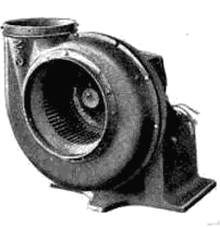
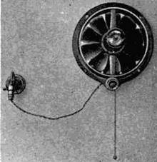
| 133. Selecting a fan. 134. The construction of the fan in common
use. 135. Ventilator. |
[10]
PART V. WATER SUPPLY AND SEWAGE DISPOSAL
| Chapter XIX. Pumps and Water Filters |
112 |
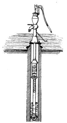
| 136. Suction pumps. 137. Care of pumps. 138. Force pumps.
139. Compressed-air pumps. 140. Water filters. |
| Chapter XX. Pressure Tanks; Plumbing Fixtures |
117 |
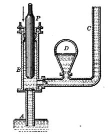
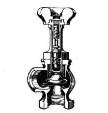
| 141. Pressure tanks. 142. Construction of the pressure tank.
143. Care of pressure tanks. 144. Hot-water kitchen tank.
145. Instantaneous water heaters. 146. Heaters for tanks. 147.
The elevated water tank. 148. Faucets. 149. Valves. 150. Overflows.
151. Traps for bath tubs and basins. |
| Chapter XXI. Cesspools, Septic Tanks and City Sewer Systems |
124 |
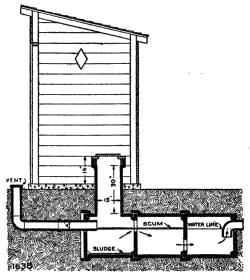
| 152. Releative value of cesspool and septic tank. 153. Construction
of the septic tank. 154. The size of tank. 155. Disposal of
waste in cities. |
| Chapter XXII. Water Closets |
128 |
| 156. Construction of water closets. 157. Siphoning the trap. 158.
The flushing tank. 159. Repairing the flushing tank. |
PART VI. LAUNDRY EQUIPMENT
| Chapter XXIII. Washing Machines |
132 |
| 160. Kinds of washing machines. 161. Suction machines. 162.
Cylinder washers. 163. Rotary washers. 164. Machine with
an oscillating washing device. 165. Oscillating washers. 166.
Locomotive washer. 167. Centrifugal washer. 168. Care of
washers. |
| Chapter XXIV. Wringers |
138 |
| 169. Roller wringer. 170. Care of wringers. 171. Centrifugal
wringer or drier. 172. Care of the machine. 173. Combination
washer and wringer. |
| [11]Chapter XXV. Mangles and Irons |
141 |
| 174. Construction of mangles. 175. Cold mangles. 176. Heated
mangles. 177. Care and use of mangles. 178. Flat, or sadirons.
179. Charcoal irons. 180. Electric irons. 181. Gas irons. 182.
Acetylene irons. 183. Alcohol irons. 184. Gasoline irons. |
PART VII. HOUSE-CLEANING EQUIPMENT
| Chapter XXVI. Vacuum Cleaners and Cleaning Tools |
147 |
| 185. Principle upon which vacuum cleaners work. 186. Different
kinds of vacuum cleaners. 187. Nozzle of vacuum cleaner. 188.
Cautions in using vacuum cleaners. 189. Difference between hand
and power cleaners. 190. Carpet sweeper. 191. Mop wringers. |
PART VIII. DEVICES FOR PREPARATION AND
CONSERVATION OF FOOD
| Chapter XXVII. Pots, Pans and Other Devices |
155 |
| 192. Materials from which Utensils are made. 193. Aluminum
alloy. 194. Cast-iron utensils. 195. Earthenware. 196. Aluminum
and graniteware. 197. Mixing spoons. |
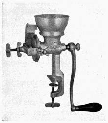
| Chapter XXVIII. Parers, Seeders, Grinders, Slicers, Etc. |
159 |
| 198. Fruit and vegetable parers and knives. 199. Parers which
grate off skins. 200. Seeders and Stoners. 201. Cherry stoner.
202. Grinders. 203. Choppers or meat grinders. 204. Choppers.
205. Slicers. 206. Lard and fruit presses, sausage stuffers. |
| Chapter XXIX. Mixers, Beaters and Churns; Coffee Pots |
165 |
| 207. Use of mixers, beaters and churns. 208. Care of these devices.
209. Freezers. 210. Care of freezers. 211. Churns. 212.
Drip coffee pots. 213. Percolator coffee pots. |
| [12]Chapter XXX. Dish-washers, Canners And Dryers |
170 |
| 214. Dish dryer. 215. Cleaning silver. 216. Canners. 217.
Water seal. 218. Pressure canners. 219. Use of the canner.
220. Dryers. 221. Care of dryers. |
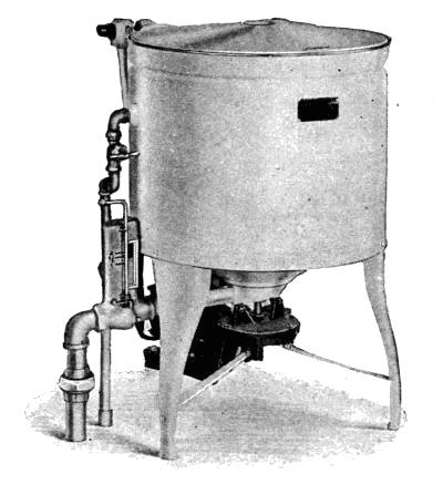
| Chapter XXXI. Separators and Emulsifiers |
178 |
| 222. Cream separators. 223. Different types of separators. 224.
Washing the machine. 225. Oiling. 226. Whey separator. 227.
Emulsifier. |
PART IX. SUNDRY DEVICES
| Chapter XXXII. Dumbwaiters and Other House Furnishings |
183 |
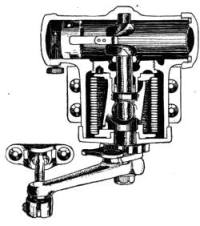
| 228. Dumbwaiters and window adjustments. 229. Check valves.
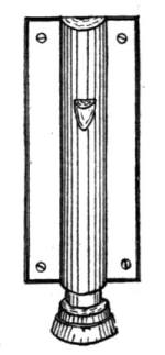
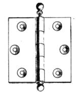
230. Door fastener. 231. Window shades. 232. Hinges. 233.
Sliding doors. |
| Chapter XXXIII. Sewing Machines |
186 |
| 234. Different types of sewing machines. 235. Lock-stitch sewing
machine. 236. Feed plate. 237. Bobbins. 238. Shuttle bobbins.
239. Chain-stitch machine. 240. Cautions for all machines.
241. General instructions. |
| Chapter XXXIV. Automobiles |
192 |
| 242. Starting the motor. 243. Driving the automobile. 244.
Care of car. |
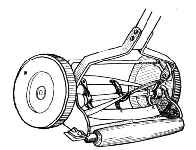
| Chapter XXXV. Lawn Mowers; Incubators |
195 |
| 245. Operation and care of lawn mowers. 246. Storing mowers.
247. Scissors and shears. 248. Principles upon which incubator
works. 249. The body of the incubator. 250. Incubators heated
by a lamp. 251. The wick. 252. Thermostat. 253. The thermometer.
254. Operation of incubator. 255. Egg tester. |
| [13]Chapter XXXVI. Typewriters |
202 |
| 256. Construction of typewriter. 257. Special features of typewriter.
258. Interchangeable-type typewriters. 259. Care of
typewriters. 260. The hectograph. 261. Mimeograph and
multigraph. |
PART X. MOTORS, FUELS AND GAS PLANTS
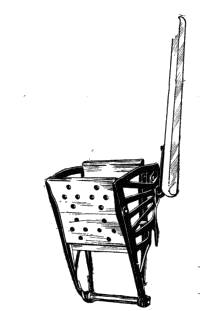
| Chapter XXXVII. Treadles and Water Motors |
209 |
| 262. Definition of motor. 263. The treadle. 264. Water motors.
265. Selecting a water motor. 266. Two types of water
motors. |
| Chapter XXXVIII. Engines; Motors and Batteries; Fuels |
212 |
| 267. Gasoline engines. 268. Figuring speed of pulleys. 269.
Operating the engine. 270. Points in caring for engine. 271.
Generating electricity for homes. 272. Batteries. 273. Liquid
batteries. 274. A dry-cell battery. 275. Storage batteries. 276.
Some uses for electric motors. 277. Definition tables. |
| Chapter XXXIX. Gas Plants |
220 |
| 278. Gasoline gas plants. 279. Acetylene-gas plant. 280. Directions
for operating acetylene plant. 281. Cautions to be observed
in using acetylene gas. 282. Compressed gases and oils. |
PART XI. MEASURING DEVICES
| Chapter XL. Scales for Weighing |
225 |
| 283. Equal-arm balances. 284. Unequal-arm balances. 285. Spring
scales. |
| Chapter XLI. Devices for Measuring Volume |
227 |
| 286. Graduate and measuring cup. 287. Tablespoons. 288. Teaspoons.
289. Standard measuring spoons. 290. Liquid and cooking
measures. 291. Dry measures. 292. Cubic, square and linear
measures. |
| [14]Chapter XLII. Gas, Water and Electric Meters |
230 |
| 293. Different kinds of meters. 294. Construction of a gas meter.
295. Reading the gas meter. 296. Water meters. 297. Prepayment
meters. 298. The electric meter. |
| Chapter XLIII. Thermometers and Thermostats |
233 |
| 299. Mercury thermometers. 300. Oven thermometer. 301. Maximum
thermometers. 302. Thermostats. |
| Chapter XLIV. Hydrometers and Barometers |
237 |
| 303. Hydrometer. 304. Hygroscopes. 305. Barometers. |
[15]
PART I
Cooking Stoves
CHAPTER I
Wood and Coal Stoves
A brief explanation of stoves is given in this chapter to help
the woman with a new stove or with an old one which she does
not understand so that she may manage it without wasting
fuel and nervous energy.
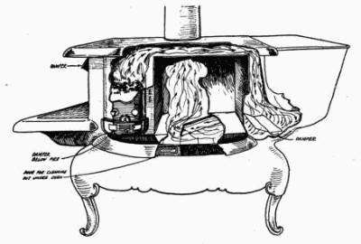
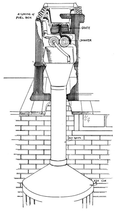
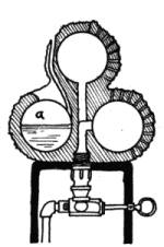
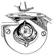
Fig. 1. Cross-section of cooking stove.
Cooking stoves (Fig. 1) were invented as a convenient
means for holding pots and pans in close proximity to the fire.
They include a device for regulating the supply of air to the
burning fuel.
[16]
1. Air Supply for Fire. A proper amount of air must be
supplied to the fuel to produce a hot fire. A smoky or yellow
flame indicates a lack of sufficient air to produce complete
combustion of the fuel. Smoke is unburnt fuel. A smoky
fire does not produce as much heat as one which burns with a
blue or almost colorless flame. It is usually not the fault of
the fuel, but the way it is being used that causes a smoky fire.
2. The Grate. Cooking stoves may be constructed for
burning either wood or coal. In both cases, the operation is
similar, except that more air should be
passing thru the stove while wood is
being burnt. For burning coal, the
grate should be less open in order to
prevent the coal from falling thru.
Some modern stoves are made with
double grates. These may be turned
so that the more open part of them is used for supporting
the wood, and the less open part for coal.
These grates are usually reversed by a stove shaker. (Fig. 1-a)
shows a detailed drawing of a grate.) The housekeeper
must understand how this is done in order to avoid reversing
them when she shakes down the ashes. Two difficulties arise
in reversing the grate when the stove is filled with fuel. The
coal may be wasted by falling thru the part intended for
wood, or pieces of fuel may fall between the parts so that they
cannot be moved. When this happens, it is best to let the
fire go out, take out the fuel, adjust the grates as they should
be and rebuild the fire.
3. Drafts or Dampers. There are from three to six
dampers on a stove (Figs. 1 and 2), as follows:
[17]
1) The draft below the fire box, found on all stoves, is to let
in air to the burning fire.
2) The draft above the fire box, not found on all stoves,
when slightly opened, lets in air which completes the combustion
of the gases arising from the top of the fire. When
opened too wide, it checks the burning of the fire.
3) The oven damper, found on all
cook stoves, is placed at the point
where the flame naturally enters
the stove pipe. When this damper
is closed, the flame must go around
the oven instead of directly up the
chimney.
To see the oven damper, take off
the lid nearest the stove pipe and
watch the direction of the flame.
The handle to the oven damper may
be at the side of the pipe on top of
the stove or at the front of the stove under the top near the
reservoir. Closing this damper causes the hot gases from
the fire to go back over the top of the stove down behind
the oven, turn under the oven and come up the chimney.
Good stoves are constructed so that the hot gases come in
contact with every part of the oven. This makes a longer
journey for the gases, but, if the drafts in the front of the
stove and chimney are properly adjusted, the gases will
make the circuit without forming soot.
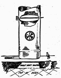
Fig. 2. Drafts and dampers
in stove-pipe.
4) A damper in the stove pipe (Fig. 2) for letting air from
the room into the pipe serves to check the burning of the fire
by taking the place of the draft thru the stove.
[18]
5) A damper, or shutter, found in the pipe or chimney of
most stoves, when closed, checks the draft up the chimney,
and, when open, lets it pass freely.
6) The reservoir damper, found on some stoves having
reservoirs, lets the hot gases pass next to the reservoir when
open and prevents this when closed.
4. Starting the Fire. If the stove has a reversible
grate, see that it is adjusted to suit the fuel before building
the fire; then adjust the drafts. Open the draft below the
fire box, the oven damper, and the shutter in the chimney;
close the draft above the fire box, and the draft which lets air
from the room into the pipe, so that the air may pass up thru
the fire box and directly up the chimney. Some chimneys
produce such strong drafts that the shutter in the chimney
has to be kept closed most of the time, even when starting the
fire. After the fuel has become ignited, the draft below the
fire may be partly closed so that it burns less rapidly. If the
fire is to be used for heating water or food on top of the stove,
it is now ready for use. If it is still burning too rapidly, the
draft may be entirely closed, or the shutter in the chimney
partly closed. If at any time the stove smokes, the shutter
or drafts above the fire may be closed too much and should be
opened enough to let all the smoke pass. Adding too much
fuel at one time and not spreading it in a thin layer over the
entire surface of the fire may cause the stove to smoke.
5. Keeping a Fire. If, after a fire has been used, it is
wanted for use later, close the draft below the fire box, open
the one above the fire box, or, if there chances to be no draft
here, tilt the lids on the stove to let in the air; close the shutter
in the chimney and open the draft in the pipe that lets in[19]
air from the room. With the drafts so adjusted, the fire
should keep a long time, as it will burn very slowly.
6. Heating the Oven. When baking is to be done, wait
until the fire is well started; then close the oven damper. The
eveness of heat in the oven depends upon the even distribution
of the hot gases below and on the sides of it. This is provided
for in the manufacture of the stove itself. The heat in
the oven may be regulated by the intensity of the heat from
the fire as well as by the damper. Whenever a cooler oven is
wanted, the flame may be permitted to go directly up the
chimney. Since hot air is always seeking a higher level than
cold air, opening the oven door cools the oven, but it will not
prevent food set on the bottom of the oven from burning on
the bottom. In a closed oven, the greatest degree of heat is
at the top, excepting sometimes the surface of the bottom of
the oven. Many stoves require the placing of a thin grating
on the bottom of the oven to prevent food from burning on
the bottom. If food does not brown sufficiently on the bottom,
remove the grating so that the dish comes in closer contact
with the heating unit.
The insulation of the oven door helps to hold heat in the
oven, but the amount lost here is so small that many housekeepers
prefer the convenience of the glass door, which, in
turn, saves heat by doing away with the necessity of opening
the oven door to watch the cooking food.
Some housewives adjust the dampers for heating the oven
and then never change them. They heat the kitchen in summer
more than is necessary and use more fuel than they need
for cooking. It has been estimated that where the careful
manager of a stove uses one pound of fuel, the careless manager
uses three and a half pounds.
[20]
One experiment station estimated that the household coal
range is used on an average of six hours a day, and, if used
carefully, seven pounds of coal is consumed. Careless management,
then, makes the waste of coal quite an item in the
course of a year, as it is not unusual for the careless manager
to use twenty-four pounds of coal per six-hour day.
There is always some soot formed, even in the best-managed
stoves, and the flame often carries ashes with it. These
in time fill the narrow space about the oven and cut off or
check the passage of the hot gases about the oven. When
this happens and the oven damper is closed, the stove will
smoke and not bake well. No stove should be allowed to get
in this condition. The housewife can watch the accumulation
of ashes in the stove and remove them before they become
one-fourth inch thick. If this is not done, the oven will
not heat well and some parts may be considerably cooler than
others.
7. Ashes. Ashes allowed to accumulate in the fire box
will cause the lining of the stove to burn out. Ashes will also
interfere with the heating of the rest of the stove. To
lengthen the life of a stove, keep the ash pan empty. If a full
pan of ashes becomes hot, it will keep the grate of the stove so
hot that it will warp and burn out, and sometimes cause
the oven to warp.
If a housewife tries to build a fresh fire in a stove with a full
ash pan, she will have to wait for the ashes to become heated
thru before she can get satisfactory use of the oven. She will
be unable to regulate the temperature of the oven if it becomes
too hot. It is a great waste of fuel to heat a large pan
full of ashes.
[21]
[22]
8. Ash Chutes. In some modern houses, there are ash
chutes which carry the ashes directly from the kitchen stove
to a receptacle in the basement (Fig. 3). These have to be
installed with care. If there is a draft of air which cannot be
regulated from the basement up thru the fire box, the fire will
burn too fast. There should be a damper to regulate drafts
here. An ash chute saves much dirt in the kitchen.
[23]
CHAPTER II
Gas Stoves
The gas stove is the simplest stove made. It consists of a
burner or burners of different shapes mounted on a suitable
frame. The best example of a gas burner is a pipe with holes
punched in it, where the gas flows out and is set on fire. This
pipe may be coiled into a circle and make a round burner, or
the holes may all come at the end, which is arranged to spread
the gas into a disc shape.
9. Burners. Stoves are usually made with different
sizes of burners. One manufacturer states that the gas
stoves made by his firm consume per top burner per hour
fourteen to eighteen feet of gas, and the oven burners consume
eighteen to twenty feet when the gas is turned on full.
Simmerers consume much less than this.
10. Simmerers. Every gas range should have a simmerer
on it. This is a small burner, usually about an inch in
diameter. After a large kettle full of food has been heated to
boiling, this burner may keep it simmering for hours, using
very little gas. This burner will keep small kettles of food
boiling.
11. Air Mixer. Gas escaping from any pipe will burn,
but it will burn with a yellow flame. To make gas burn with
a blue flame—that is, to secure complete combustion—air
must be mixed with it. This is done in the air mixer (Fig. 4).
The blue flame is desirable for cooking because it is hotter
than the yellow flame and does not blacken the cooking utensils.
[24]
Gas passes thru the air mixer before entering the burner.
Sometimes the air inlet is only a hole put in the under side of
the pipe. The opening for entrance of air is shielded so that
the gas will not escape from the mixer, but will go on into the
burner. A gas pipe looks about half an inch in diameter, but
the stream of gas which is allowed to flow into the burner is
very small, in some cases being about
the diameter of a darning needle.
The opening for air is so large, that
a person's finger may be put into it.
Too much air interferes with the
burning of the gas; in fact, there can
be so much air mixed with gas that it
will not burn. The air mixer regulates
the amount of air which flows
into the pipe. Once this is adjusted
for the kind of gas to be used, it seldom
needs to be changed. The air
shutter has to be changed, however,
if the gas pressure varies markedly from time to time. Readjustment
may be required if the stove is moved and connected
with a different supply of gas. When adjusting the
mixer for high pressure, artificial or natural gas, close the
shutter until the flame will not blow away from the cone, but
will burn with a blue, almost colorless, flame.
Fig. 4. Part of gas stove
showing air mixers.
12. Regulating the Gas. The amount of gas which
passes into the stove is also regulated, first, by adjustment of
the size of the small opening thru which the gas must flow.
Once this is adjusted, it does not need to be changed so long as
the gas comes from the same source. Second, the flow of gas[25]
is regulated by the lever valve. As the valve is turned, the
flow of gas is restricted so that it flows less swiftly. The size
of the stream of gas going into the stove always looks the same
regardless of its speed. When the rate is not so fast, the fire
burns lower because less gas comes to it during every unit of
time.
13. Lighting the Stove. Light the top burners by first
striking a match, and then turning on the burner so that
there will be an unrestricted
flow of gas. Count three before
applying the match. This
gives time for the burner to fill
with gas. If the match goes
out, shut off the gas and try
again. If it burns back into
the air hole, also turn off the
gas and begin again. Probably
the match was applied too
soon. Gas stoves get out of order because of carelessness
in lighting them. The force of the explosions caused in
burning back loosens connections and may disturb the adjustment
of the mixer and valve.
Fig. 5. Cleaning gas stove.
14. Cleaning the Stove. Housekeepers should keep
their gas stoves clean. Dirt interferes with the passage of the
gas thru the burners. Gas stoves should be cleaned thoroly
once a month. Scrub the burners with a stiff brush (Fig. 5),
and wash all greasy parts with soap and water. If the holes
should be clogged, remove the stoppage with a wire hair-pin
(Fig. 6). Clean the drip sheet every day, or as often as it becomes
soiled. (Fig. 4.)
[26]
15. Accidents with Gas Stove. Accidents with gas
stoves are the result of mismanagement. The odor of gas in a
room indicates a leak in the gas fixtures, such as stoves or
pipes. When such an odor is noticed, open windows and extinguish
all fires in the room or building. Next search for the
leak. It may be due to an open valve. See that these are all
shut tight. If no valves are open, send for a plumber who
looks after gas fixtures. Leave the windows open and do not
carry lighted matches or
lamps into the room until
the leak has been stopped.
Fig. 6. Cleaning burner of gas stove.
Many accidents happen
at the time the oven is
being lighted. Sometimes
gas escapes into a closed
oven, so that its odor is
not noticed in the kitchen.
This gas catches fire or explodes
when the oven
burner is lighted, blowing the oven door open or off the
hinges, flashing out of the oven, and burning any person near
the stove. To avoid such accidents, always open the oven
and broiler doors a few minutes before lighting the oven.
Fig. 7 shows construction of gas-stove oven. If any odor
of gas is noticed on opening the doors, fan this out. Leave
the oven and broiler doors open a while after extinguishing
the fire and removing the cooked food. Gas may get into
the oven at the time the flame is extinguished.
16. Pilot Light. Most stoves are constructed so that
there is a pilot light for the oven. Always use it when lighting[27]
the oven. It is put there for the safety of those using the
stove. There is no need for alarm when a pilot burns back,
no matter how much noise it makes, since so little gas flows
thru the opening. One of
the functions of a pilot
light is to prevent people
from being burnt in case of
an explosion in the oven.
For this reason, they
should be at the side of
the stove.
If the pilot burns back,
close it; wait a minute, and
then try lighting it again.
The regular burners of the
stove should not burn back
if properly lighted by the
pilot. Be careful to see that every part of the oven burner
becomes lighted. Turn
the burners on full
while lighting them.
After they are once
lighted, turn them as
low as desired.
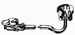
Fig. 8. Pilot light for gas stove.
17. Pilot for Top Burners. A pilot made for top burners
(Fig. 8) burns continuously with a very tiny flame. Its
purpose is to save gas, patience, dirt and matches. The
saving comes because the housekeeper can so easily re-light
the burners that she will turn them out whenever she is not
needing the fire. Sometimes when the gas pressure is low,[28]
the pilot light will go out. It can be re-lighted by pressing
the valve as for lighting the burners and touching a match to
it. If the pilot goes out, the odor of gas will be noticed in the
kitchen until it is re-lighted.
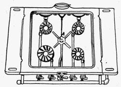
Fig. 9. Top view of gas stove,
showing lighter.
18. Gas-Stove Lighter. There are two kinds of gas-stove
lighters. These differ from the pilot in that they do
not burn constantly. One
of these is so constructed
that it is first necessary to
apply a match to any one of
the top burners. The other
burners can then be lighted
by opening the valve in the
regular manner and pressing
down on the lighter
knob. As soon as pressure on the lighter knob is removed,
the gas supply to the lighter is automatically cut off
(Fig. 9). The other lighter is made of metal which gives
sparks easily when subjected to friction. The lighter is held
over the stove, the gas turned on and the friction produced
by rubbing one part of the lighter across the other, making a
spark which ignites the gas.
19. Amount of Gas Used. It is claimed that 1,000 feet
of illuminating gas produce as much heat as 50 or 60 pounds
of anthracite coal or 4-1/2 gallons of kerosene oil. (See table
on page 219.)
The difference in gas bills, due to management of gas stoves,
is considerable. It is very easy for one woman to use three
times as much gas as another in doing the same amount of[29]
work. Some women do not realize when they are wasting
gas.
Water boils in an uncovered vessel at 212 degrees Fahrenheit,
and no amount of heat applied to it will make it any hotter.
When a pot of food has reached the boiling point, a
smaller flame will keep it boiling. Turn the gas as low as it
may be safely turned and still
keep the pot boiling, and the
food will cook as rapidly as
when the gas is turned on full.
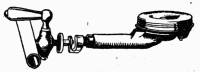
Fig. 10. Single top burner
and valve.
Gas is a safe fuel in most
hands; it saves the housekeeper much labor because it makes
so little dirt. When properly managed, it is the cheapest
fuel to be had at the present time.
20. Cold-Process Gasoline Gas Stoves. Cold-process
gasoline stoves require a burner fitted with valves in which
the gas orifice can be enlarged
or diminished. The
best of these for using cold-process
gasoline gas can be adjusted by a turn of the finger.
The adjustment of the valve is to compensate for the neglect
upon the part of users of these plants. Very frequently
they will allow the supply of gasoline in the carburetor to run
nearly out before they replenish it, in which case the gas
comes to the burners in a thinner quality, and in order to provide
the same volume of heat, it is necessary to adjust the
burner valves and throw a larger stream of gas into the
burner. They are sometimes fitted with burners having side-sawed
caps (Figs. 10 and 10-a). These seem to expose the
burning gas to the air in a way to make it burn better than in[30]
other burners built for gas forced into them by greater pressure
than is this gas. The opening for air must be adjusted
from time to time so as to keep the proportion of gas and air
such that it will produce a blue flame.
21. Acetylene Stoves. Stoves for the burning of acetylene
are similar in construction to gas stoves. The acetylene
furnishes a satisfactory and economical light, it is not an
economical fuel when compared with kerosene, gas, wood or
coal. For this reason, it is not much used. It requires two
and three-tenths units of acetylene gas to equal one unit of
natural gas for heating.
[31]
CHAPTER III
Oil Stoves
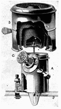
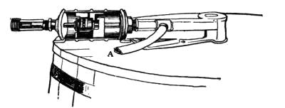
Fig. 11. Parts of oil stove
burner.
22. Purpose of Oil Stoves. Oil stoves are designed for
the comfort of the woman who cannot have a gas or an electric
stove. They consist of tank, feed pipe and burners (Figs.
11-a and 11-b). As they are portable, they can be moved to a
summer kitchen or sheltered back porch on hot summer days.
Oil stoves are not fool-proof and
should never be used by those who
are afraid of them and who do not
understand them. Manufacturers
have done much to make accidents
avoidable, and they send detailed
instructions with each stove. These
should be followed exactly.
23. Mechanical Parts of Kerosene
Stove. The kerosene oil stove
consists of a tank of oil with a pipe
leading to a hollow ring-like cup below
the burner (A, Fig. 11). When
the burner is lighted, the oil passes
down this pipe into the ring, where
it becomes heated and is vaporized.
As the vapor rises, it is mixed with
air and burns with a blue flame. The small holes in the
chimney of the burner and at the base of the burner are to
admit air. They must be kept open.
[32]
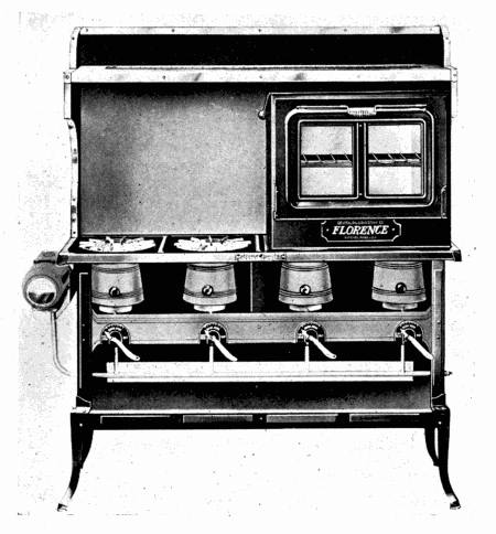
Fig. 11-a. Large oil stove with oven.
If the burner is dirty or not properly adjusted, the right
amount of air may not reach the vaporized oil to mix with it
and the stove will burn with a yellow flame, making soot and
smoke.
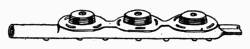
24. The Burner. The burner consists of a chimney, a
wick or ring of asbestos, a valve or a lever, and a ring-like cup
at the base of the burner. There are three distinct types of
burners known as long chimney, short chimney and wickless.[33]
The wickless stoves are equipped with a ring of asbestos
which serves the purpose of a wick.
Fig. 11-b. Oil stove
without
oven.
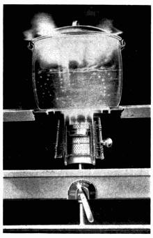
Fig. 12. Oil stove burner,
showing
fire close to utensil.
————
The burners on one oil stove are usually all alike. The
burners on various makes differ.
Those in which the flame
comes nearest the kettle or
cooking food produce the most
heat for cooking (Fig. 12).
Those with the blaze farther
away from the food seem to be
easier for the excitable woman to manage (Fig. 13).
25. The Chimney. Kerosene stoves are furnished with
metal chimneys. A device for mixing air with the burning
fuel forms a part of short chimneys (B, Fig. 11). The chimney
must set on the burner properly, or the stove will not
burn with a blue flame. After lighting a burner, give the
chimney a turn or two to make sure that it is in place. There
is usually a groove into which it fits.
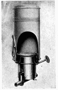
Fig. 13. Burner for
oil
stove.
26. Lighting the Stove. When lighting a stove, turn
the valve which permits the oil to flow (C, Fig. 11) into the[34]
cup below the burner, or lower the lighter into the oil. Wait
a moment, if need be, for the wick or ring to become saturated
with oil. Raise the chimney and touch the lighted match to
the ring or wick at several places. (Fig. 14, and Fig. 11, also,
show the position of the chimney
and wick for lighting.) Lower the
chimney, seeing that it fits back into
place. Adjust the wick to the proper
height to get a blue flame (Fig. 15).
Do not turn very high at first, for, while
the stove is becoming heated, the flame
burns higher and higher, and may begin
to smoke.
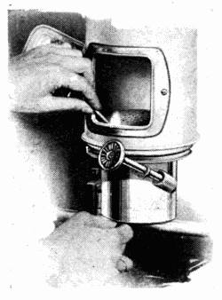
Fig. 14. Lighting oil stove.
————
27. Management of the Flame.
Turn the flame no higher than is
needed to keep the pot boiling. Some
stoves do not burn well when turned
very low. Do not have the flame
so high or so low that it gives off
smoke or gas. When turning out
the fire, be sure to turn the wick
clear down, or turn the valve or lever
(Fig. 12) to the point indicated as
out on stoves which lift the ring above
the oil. If this precaution is not
taken, most stoves leak oil when not
in use, because the wick or rings carry
oil to the upper part of the burner
where it spreads over the stove.
28. Adjustment and Care of the Stove. To prevent[35]
trouble with uneven flames, set the stove perfectly level, particularly
the wickless one. Keep the tank filled, but not too
full. Stoves are made so that it is difficult to fill them too
full. An oil stove cannot explode unless gas has formed in
some part, like the tank, and becomes ignited by heat or a
spark. Gas is more likely to collect
in the tank when it is almost
empty.
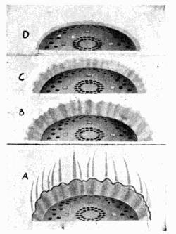
Fig. 15. Different types of
flames.
When the tank is removed for
filling, any gas forming passes out
into the room and mixes with so
much air that it is harmless. If it
is filled before the oil burns out of
the pipe above the level of the
burners, no gas will be formed.
Stoves must be kept clean. A
clean stove means one with a clean
framework, clean burners, clean
chimney, clean oil and a clean
wick or ring.
If a stove has not been in use for some time, replace the old
wick with a fresh one (Fig. 16). Clean the stove by wiping
off all the parts with a cloth. Keep the charred edges of the
wick trimmed level. The wick with a crust of char on top
does not burn well. Use a match or small stick in removing
the char. Light the wick to see if it is even. If any point
burns with a yellow flame, trim this place until the wick burns
even. The tank can easily and quickly be lifted off modern
oil stoves. Do not refill near a lighted stove.
29. When the Stove Gives Trouble. In case the stove[36]
begins to blaze and cannot be controlled by the valves, remove
the tank and carry it to some safe place where the kerosene
in it cannot catch fire. When this is done, there is less
than a pint of oil left in most stoves, and this will soon burn
out without doing much harm, if clothing and water are kept
away from the blaze. Open windows
and doors to let out gases
and smoke. If necessary, move the
stove away from walls or furniture.
Do not attempt to smother out the
flame. There is too much danger
of clothing catching fire when this
is done. It is far safer to let the
small amount of oil left in the stove
burn up. Oil stoves cannot explode
when the tank is removed.
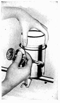
Fig. 16. Inserting new
wick.
As soon as the oil has burnt out
of the pipes and the wicks are
burning with a dull glow, extinguish
the smoldering fire on the wicks by
patting them with the blade of a knife or a piece of woolen
cloth.
If a burner has been blazing beyond control, remove the
chimney. Brush out any soot which has formed. Examine
the burner, taking it apart, if possible. Blazing may come
from wicks not fitting, or from their getting so short that the
screw on the lever fails to move them up or down. The ring
in wickless stoves may not be thick enough, or they may have
slipped out of place, or become broken. Replace with new
wicks or rings.
[37]
Notice if any part of the burner shows evidence of
melting. If it does, do not use this burner until inspected
and mended by an expert. If the lever has become worn so
that it fails to work, it must be replaced or a new burner put
on the stove.
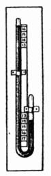
30. Construction of Gasoline Stoves. The gasoline
stoves consist of a burner and an oil tank connected by a pipe
(Fig. 17). The tank is elevated for
the purpose of forcing the gasoline
into the burner. The pipe may be
any length. The danger from a gasoline
stove comes from the fact that
gasoline vaporizes at a low temperature.
If the tank becomes heated,
producing gas, and then becomes
mixed with the proper proportion of
air, it may explode if it comes in
contact with a spark. (Fig. 17-a is
an illustration of the cross-section of
the Red Star gasoline or vapor stove.
See page 38.)
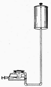
Fig. 17. Simple
gasoline
burner.
From the pipe to the burner is a
very small opening, so that a stream of gasoline little larger
than the diameter of a needle flows into the burner proper,
when the valve is open. The valve may be partly closed so
that the stream will not flow so fast.
Below the burner is a small cup. When the stove is cold,
the gasoline flowing into the burner collects here.
31. To Light the Stove. The way to light the stove is
to turn on the gasoline until it fills the cup below the burner.[38]
When this is full, close the valve. Set this gasoline on fire.
As it burns, it will heat the burner.
The burner is heated so that when more gasoline is turned
on, this heat will change the gasoline to gas. If the burner is
not hot enough to do this, the gasoline flowing from the pipe
will flow down into the
cup and the stove will
burn with a smoky flame
which becomes higher and
higher and looks very
alarming.
When this happens, the
valve should be closed,
and the fire permitted to
burn all the gasoline which
has collected in the cup.
This may be sufficient to
heat the burner. Test
after the fire has gone out,
by lighting a match, turning
on the gasoline and
touching the lighted match
to the burner. If all right,
it will burn with a blue flame; if not, it will burn with a
yellow flame. If the yellow flame is noticed, turn out the fire
by closing the valve, and let the burner get cold before attempting
again to light it. See that the burner has not become
clogged with soot or dirt. Then proceed to re-light the
stove.
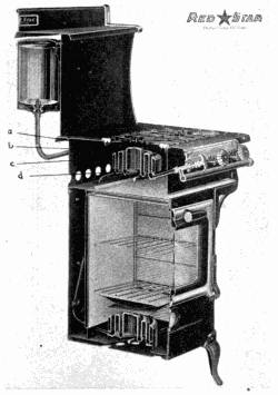
Fig. 17-a. Cross-section of gasoline
stove showing burner.
Air must be mixed with the gasoline to make it burn with a[39]
blue flame. The air enters the burner through the same tube
that the gasoline flows into the cups when the burner is cold.
In the burner are small holes for the escape of the gas mixed
with air, and here the blue flame should appear, and nowhere
else. If it appears elsewhere, the burner is not working properly.
Sometimes the gas ignites at the point where the air is
mixed with it. The fire should then be turned out and the
stove re-lighted immediately.
If the little holes where the flames should be, or if any other
part of the stove is clogged with soot, it will not burn as it
should. It must be cleaned. A dirty gasoline stove is dangerous.
32. Filling the Gasoline Stove. Never get oil on the
tank or any part of the stove while filling it. If oil is spilled,
wipe it up before igniting the stove. Do not fill the tank
when the stove is lighted or when there is a fire anywhere near
the tank. If the fire has been burning, close all the valves
and wait until it goes out before opening the tank. Close the
valve from tank to pipe before filling. Fill the tank and cover
it before lighting the stove again.
Keep the tank filled. As soon as the indicator, which is
attached to a cork which floats on top of the gasoline, shows
that the oil is low, turn out the fire and refill the tank. Do
not fill the tank to overflowing. Gases from the stove can
only get into the tank when it is empty and while there is gasoline
in the pipe to feed the stove. Gasoline gas is very inflammable
and will cause an explosion if it becomes ignited.
The tanks from gasoline stoves cannot be removed, as all the
joints must be tight to prevent the escape of gasoline fumes
as well as the oil itself. The opening to the tank must never[40]
be left uncovered, except for the few minutes while the tank
is being filled. The greatest care is required in using a gasoline
stove; in fact, they are so dangerous, that they should not
be highly recommended for household use. The description
and care of them are given here because some persons persist
in using them when they desire a quick, hot fire in cases where
fuel gas is not available.
33. When a Burner Blazes and Cannot Be Controlled.
When a gasoline stove burner blazes and cannot be controlled,
first close the valve leading from the tank into the pipe.
There will then be little gasoline to burn, and no gases can
get back into the tank.
Keep clothing and water away from the blaze. Remember that
the stove is set on a metal frame which is not inflammable.
Shield walls and other objects so that the burner may blaze
high without doing damage. Clothing catches fire easily,
but the metal stove will not be consumed.
If the valves are shut, the blaze will cease when the gasoline
has burnt out of the burner and pipe. If the gasoline continues
to flow out of the burner in spite of turning the valve and
there is a danger of its spreading to the floor or table, set a
shallow pan under the stove to catch the gasoline. It can
burn in this way with considerable safety. Do not attempt
to carry a burning stove. Simply protect floor, walls and furniture
from catching fire, and let the gasoline burn.
34. Changing Fuel in Vapor Stoves. There are some
stoves which are interchangeable, in that they may be adjusted
to burn kerosene, gasoline or distillate. These are of
the type called "vapor" because they change the oil to gas before
it is ignited. A change from one kind of fuel to another[41]
should never be made without thoroly cleaning the stove and
adjusting it to the fuel that is to be used.
35. Operation of Vapor Stoves. It is safest to use
kerosene in these stoves. Distillate is a name given to a different
mineral oil product from kerosene or gasoline. To
work well, these burners must be kept clean. (Fig. 17-a.)
The operation of the stove is simple. Put enough fuel,
such as alcohol, into a burner to heat it hot enough to change
the oil to be used to gas and ignite it.
After the burner has heated for three or four minutes, turn
on the fuel valve in the pipe which leads from the tank to the
burner. The fuel will light from the burning alcohol already
in the burner. Adjust the height of the flame by valve,
which regulates the amount of fuel flowing into the burner.
If anything boils over, put out the fire. Close the valve.
Remove the parts of the burner. Clean and wipe them dry.
Replace the parts of the burner, and, if not cool, turn on the
fuel and light. If cool, heat as for first lighting, and turn on
the fuel.
Extinguish the fire by closing the valve which stops the
flow of oil to the burner.
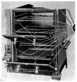
[42]
CHAPTER IV
Electric Stoves
Electric stoves consist of frame, heating unit and switches
to regulate the flow of current. Some are equipped with
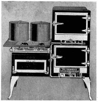
oven, thermometers and special utensils (Fig. 18).
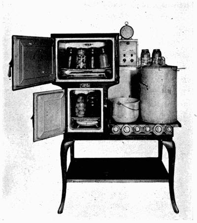
Fig. 18. Stove equipped with utensils.
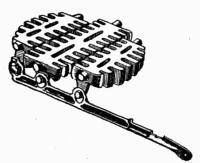
36. Heating Unit of Electric Stove. The heating unit
consists of coils of wire or a plate of metal thru which the current
flows, meeting resistance and producing heat. If the[43]
current flowed freely thru the wires, little heat would be generated
(Figs. 19 and 20).
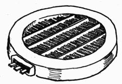
Fig. 19. Heating unit of
electric stove.
37. Wiring of Stoves. It is advocated that a separate
circuit of heavy wire be put into all houses where current is
used for purposes other than lighting,
to provide for cooking and power
connections.
Too heavy loading of wires with
electric appliances causes the burning
of fuses and sometimes damages the
electric system. Find out how much
current the wiring of the house will carry before attaching
new devices. There is danger of fire if too much current is
allowed to pass over a wire of too small size.
38. Operation of Electric Stoves. Many stoves are
equipped with a switch which permits different amounts of
current to pass thru the stove according to the way the device
is set. At one point it gives low heat; another, medium, and
a third, high heat, and, lastly, no heat.
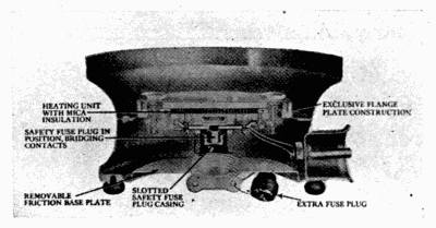
Fig. 20. Heating unit of electric stove.
The cooking of food on an open burner should be started[44]
with high heat turned on so that the food may cook quickly.
If a large amount of food is cooking, there will be so much
radiation from the vessel that it may require all the current
to keep it cooking. After food has started cooking, the switch
can be turned to medium, and, later, to low, depending upon
the amount of food and the temperature desired. Low will
keep an ordinary pan of water boiling, once it has started.
A few minutes before the food is to be removed from the
open burner, the current should be turned off, as the heat in
the stove will continue the cooking for several minutes. From
tests of electric stoves, it appears that in most of them the
food will continue to cook after the switch is turned off for
about the same number of minutes that it requires to raise the
heating unit to a temperature sufficient to boil water in a
small shallow pan. A housekeeper who is using electricity
for cooking can soon learn how long the open burners and
oven of her stove will keep food cooking after the current is
turned off, and by putting this information to use, she can
save many dollars in a year.
39. Care of Electric Stoves. When thru with a stove,
always turn off the current. Great care should be taken that
the stoves do not become overheated. This shortens the life
of the stove.
Sudden cooling of the coils of wire caused by liquids spilling
on them, and corrosion of the wires caused by dampness, wear
out stoves faster than need be. Do not wash or brush dirt
from burners having open coils of wire. Burn all dirt from
the burners.
40. Utensils for Electric Stoves. The most economical
use of electricity can be secured with utensils built around the[45]
heating units (Figs. 20 and 21), and the next most economical
use with utensils built especially to fit the heating units. This
means that there would be a heating unit for each utensil, or
size of utensil, and the expense of equipment would be considerable.
Also, more care would be needed in washing the
utensils and in preventing
them from becoming bent.
Such facts must be considered
in choosing between
stoves with special devices
and those on which any pan
may be set. After installing
an electric stove, start
with new utensils because
they will not blacken on
an electric stove, and so can be washed with the other
dishes.
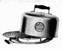
Fig. 21. Utensil with heating unit.
When ordinary household utensils are used, they should be
of such shape that they stand flat, as they also should on a coal
range. The most economical use of heat is secured when the
area of heat is smaller than the area of the bottom of the kettle
and is concentrated on the utensil. Care should be taken
when stoves are installed, that they are properly grounded so
that they cannot burn any one. A light bulb is attached to
some stoves so that when the current is on the light burns,
and when it is off, the light goes out. Such a light should be
on all large stoves.
41. Detachable Cooking Devices. Cooking and heating
devices should have larger wires than those for lighting
alone. Consequently, the attachment of a heating device in[46]
a common light socket may cause burning out of fuses or other
damage.
One danger in using detachable electric devices occurs in
not turning off the current when the stove is not in use, thus
permitting it to become overheated. This shortens the life
of the stove.
Any tendency of a stove or other electric device to give
people a shock when being used should be taken as a warning
to have the device examined by an expert and the trouble
corrected. Have the wires repaired as soon as the insulation
breaks or burns off. Uninsulated wires, such as cables and
cords, are unsafe.
[47]
CHAPTER V
Alcohol, Acetylene, and Canned Heat
42. Alcohol Stoves. Alcohol stoves are made only in
small sizes for light housekeeping. There are three general
types of these—those which burn with a wick, those which
generate gas, and those which permit the alcohol to burn off
of the top surface of the container.
Alcohol does not produce much smoke in burning, even
when no provision is made for mixing air with it. The ordinary
alcohol lamp, having a wick, may be used as a heating
stove. Stoves with wicks draw the alcohol up by capillary
attraction to the point of ignition, and the metal jacket about
the wick prevents the fire burning back into the bowl containing
the alcohol. The char from the top of the wick must
be brushed off from time to time. No other care is needed
for these stoves or lamps. Some of them are provided with
devices for checking the burning of the alcohol in order to
regulate the heat. This is desirable since a small flame of
alcohol produces much heat.
Extinguish the fire by covering the wick with a metal cup.
43. Vapor Stoves. Alcohol vapor stoves which generate
gas hold the alcohol in a tank slightly raised above the level of
the burner. A pipe leads from this to the burner, where a
small stream of alcohol is permitted to enter when the valve
is open.
When starting these stoves, the valve is first opened and
enough alcohol allowed to flow out to fill a cup which is below[48]
the burner. This generally holds about a tablespoonful of
alcohol. When the cup is full, the valve is closed and the
alcohol in the cup ignited.
This heats the burner enough to vaporize the alcohol.
When the burner is heated, open the valve and ignite the gas.
If all the alcohol is not vaporized, the burner has not been
heated hot enough. Close the valve until all the alcohol in
the cup is burnt.
44. Wickless Stoves. Wickless alcohol stoves are used
commonly on chafing dishes. The burner of one type consists
of a metal dish packed with a porous material which is
non-inflammable, but a good conductor of liquids by capillary
attraction, and the top is covered over by a wire screen. The
alcohol is poured into the dish. The packing and screen prevent
air from entering the bowl with sufficient rapidity to let
the fire burn below the screen so the flame stays above it,
burning off any alcohol which is conducted to the surface.
The only possible way to control these stoves is by a device
which can cut off air. One of these is a plate-like device with
a handle. This fits over the stove and only that portion of
the top burns which is exposed to air through the hole in the
plate. Making the hole larger or smaller makes the burning
surface larger or smaller.
To extinguish the fire, cover the entire top with a solid
plate to cut off all air.
45. Canned Heat. Canned heat is alcohol combined
with other substances into a cake about the consistency of
hard soap. The cover to the can is used to extinguish the
fire. It should not be fitted into the top of the can until the
flame has been extinguished for two or three seconds. Then[49]
it should be fitted on as tight as possible to prevent waste
alcohol by vaporization.
46. Acetylene Gas Stoves. By adjustment of the
amount of air that enters the burner, acetylene may be burnt
in a gas stove. Usually a cap is placed over the air hole
while the gas is being ignited. This is removed as soon as the
gas is lighted, so that it will burn with a blue flame. The use
of the cap prevents burning back. It is best, however, to
use stoves especially designed for burning acetylene.
[50]
CHAPTER VI
Fireless and Steam Cookers
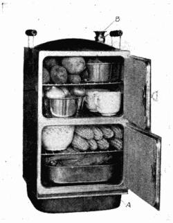
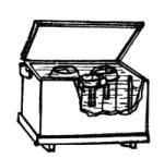
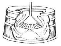
47. The Fireless Cooker. The fireless cooker is a box
or can having a diameter somewhat larger than that of the
largest vessel to be placed in it. The space left around the
vessel is packed with some insulating material to keep in the
heat (Fig. 22). In home-made cookers, this material may be
hay, feathers, pillows, shredded newspapers, wood shavings
or sawdust. In commercially-made cookers, it is felt, asbestos
wool, cork, or other insulating material. Because most
insulating material will not stay in place and readily absorbs
moisture and odors, some kind of lining is put between it and
the vessel holding the food. This makes a little nest, into
which the vessel fits. In the better made cookers, this lining
is made of metal, and the seams are water-tight.
The steam from the cooking food is absorbed by the insulating
material if this lining is not impervious to water.
Enameled or earthen linings, if well glazed, would also serve
this purpose as long as they did not chip or crack.
The cover, as well as the sides, of the fireless cooker has to
be padded with the insulating material. The cover must also
fit well so that the steam and heat will not escape thru cracks
between it and the body of the cooker.
48. The Stones of Fireless Cookers. The stones for
fireless cookers are usually made of soapstone or some composite
which will absorb considerable heat. They should be
slightly smaller in diameter than the nest. They can only be
used with safety in cookers which are metal-lined and insulated[51]
with material which will not ignite at a low temperature.
Stones should not be put in home-made cookers which are not
insulated with asbestos or other fireproof material. Hot
stones can be used with safety in any of the commercial cookers
which come fitted with them.
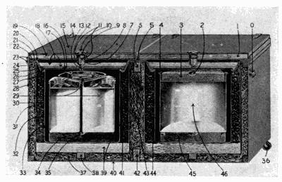
Fig. 22. Section of fireless cooker.
The temperature in a fireless cooker is below boiling most
of the time. It is, therefore, a device for simmering food,
and should be used for cooking meats, fruits, vegetables and
cereal dishes which require or are improved by long, slow
cooking.
Since the food has to be shut in a fireless cooker to keep in
the heat, fireless cookery is a method of steaming of food.
For this reason, it has a slightly different flavor from food
baked in the oven, much as fried food differs from roasted
food. Hot stones (Fig. 22) are put in most fireless cookers.
The heat from these brown the food and give to the otherwise
steamed food a flavor similar to that developed in baking,
roasting and frying.
[52]
49. Heating the Stones. Moisture given off by the
cooking food is absorbed by the stones. They must be dried
or heated very slowly to prevent this moisture from cracking
them. When the stones have been removed from the cooker,
wash them, because they absorb odors from the food. Keep
them in some warm, dry place while they are not in use, such
as in the warming oven of the cook stove or on a radiator.
When wanted for use, they will then be dry enough to be
placed over the gas-stove burner if it is not turned too high at
first. Drying thus saves time when the stones are needed.
50. Care of the Cooker. The cooker should be left
open to air while not in use. As soon as the food and stones are
removed from it, the moisture should be wiped out and the
inside washed with soap and water, wiped dry and left to air.
Such care is needed to prevent the cooker from taking on the
odor of dishes previously cooked and transmitting some of
them to those cooked later.
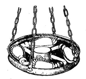
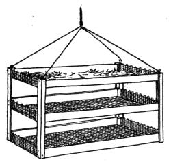
51. Other Devices Belonging to Cookers. In most
commercial cookers there are wire devices to raise the dishes
of food from the stone (Fig. 23). This prevents scorching and
boiling over when the stones are heated very hot. These devices
are also used to hold a hot stone above the food to make
a brown crust on it. Some cookers are furnished with valves,
permitting the escape of steam when it becomes too abundant.
The pressure of the steam automatically opens the valve.
This device insures the cooking of certain vegetables, cereals
or doughs without their becoming too soggy to be palatable
(A, Fig. 23).
52. Directions for Using the Cooker. Put the stones
on to heat. Prepare the food as for cooking in any other way.[53]
Then heat it, either in the oven or on top of the stove. It is
preferable to heat the food in the same vessel in which it is to
be cooked in the fireless cooker. Transferring food to a cold
vessel entails a loss of heat, since the first vessel is already
heated.
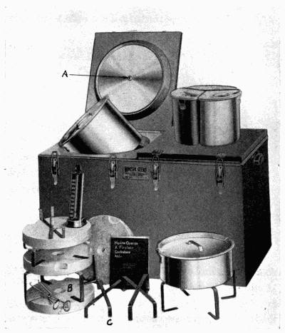
Fig. 23. Devices for fireless cooker.
When the stones and food are hot, place the stone in the
bottom of the cooker. Put in any asbestos mats or other[54]
devices which are needed to protect the food. The stone should
be hot enough to respond to the test for flat irons. It should
make the snappy noise of a good hot iron when the finger is
moistened and touched to it. Place the food in the cooker.
Place another stone above the utensil if it is desirable to have
the food brown on top. Close the fireless cooker, and let it
stand until ready for use.
53. Time of Cooking Food. Six hours or over night
should be allowed for the cooking of cereals. Stews should
be given two to three hours' time for cooking.
Large roasts and hams require five to six hours. It is
sometimes necessary, when they are large, to remove them
and heat the food and the stones on the stove once during the
process of cooking. Dumplings and angel cakes cook well in a
fireless cooker. So do all dried peas and beans.
[55]
It is profitable to cook foods requiring more than forty
minutes' heating in a fireless cooker. The heating unit is a
part of some cookers.
Electric cookers, instead of being furnished with stones to
be put inside the nest, have a heating unit and plate for holding
heat in the cooker.
Cold food may be put into
this cooker, the current
turned on, and the heating
and cooking all be
done inside the cooker.
The electric oven which
is well insulated answers
the purpose of a fireless
cooker when the current
is disconnected. Either a
thermometer, which the
housewife may watch, or
thermostat, which controls
the current, must be
attached to electric cookers
to prevent burning
the food or injuring the cooker with too much heat.
54. Gas Cookers. Since heated air rises, special cookers
in the form of insulated caps are made to put over dishes of
food heated on gas burners (Fig. 24).
The inside of the cap must be kept clean. Get the dishes
hot with the cap suspended over the food, but leaving about
an inch space for the escape of gases from the heating unit.
As soon as the food and cap have been sufficiently heated[56]
over the fire, turn off the gas and lower the cap so that it will
retain the heat. After the cooker has been used, it should be
wiped out clean; otherwise it will retain some of the odors of
the cooked food.
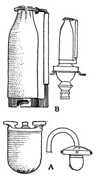
55. Steam Cookers. There are several steam cookers
in use in homes. The simplest of these is a covered pan
which has a perforated bottom, which is set over another pan
(A, Fig. 25), in which water is placed for forming steam. One
of the difficulties of this cooker is that the water in the lower
pan cannot be watched and may boil dry. On the more improved
cookers a whistling device (B, Fig. 25) is attached to the
pan, and when the water becomes low and steam ceases to
flow through it, air begins to come in, and the device makes a
whistling noise.
Questions for Part I
1. What is smoke? Under what conditions is the greatest amount
of heat for cooking or other household purposes produced from fuel?
2. How is an oven made to heat evenly?
3. Explain the purpose of each draft and damper on a stove.
4. Observe the amount of fuel used in a coal stove from day to
day. Make the same kind of observation for a gas or electric stove.
How was the stove managed when the least fuel was used?
5. Describe the construction of a gas stove. Find the vent thru
which the gas enters the burner. Is this large or small?
6. Where is the air regulator? For what is it used?
7. What has happened when the gas in a burner "burns back"?
8. How should a kerosene stove be regulated? How should it be
cared for?
9. What precautions should you take against fire from kerosene and
gasoline stoves?
10. Describe the heating unit of an electric stove.
11. How may electric current be saved in the operation of an electric
stove?
12. How does a fireless cooker cook food?
13. How may one determine when it is economical to use a fireless
cooker?
[57]
PART II
Heating Devices
CHAPTER VII
Warm-Air Furnaces
56. Principle Upon Which a Furnace Works. The
success of warm-air heating depends on a natural circulation
of air thruout all the rooms which are to be heated. The air
is the vehicle of transmission of the heat from the fire to the
rooms to be warmed.
A warm-air furnace is simply a large stove encased in a
sheet-metal jacket (Figs. 26 and 27). The jacket is usually
insulated with asbestos, since the stove is set in the basement
where radiation of heat is not desired. The air entering the
casing is warmed by the stove. As the air is warmed, it expands
and becomes lighter, so rises to the top of the furnace;
from here it is conducted to the rooms above. The warm air
which has passed upward must be replaced by cooler air entering
at the bottom of the jacket. In the rooms above, there
must be outlets for the cold air, already in them, so that it
may be replaced by the incoming warm air. Cold-air shafts
from the floor leading downward serve as outlets. Sometimes
they return the cooled air to the base of the furnace
jacket.
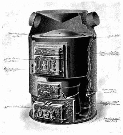
Fig. 26. Warm-air furnace.
57. The Stove Part. The stove part of the hot-air furnace
consists of a fire pot supported above a place where the
ashes may fall and a chimney to carry off smoke. The draft[58]
below the grate in the fire pot lets in air which is essential to
the proper burning of the fuel. In this respect, it is similar
to a cook stove. A draft above the fire when opened a little
lets in air which aids in the complete combustion of the gases
given off by the fuel. Burning these gases adds to the amount
of heat secured from the fuel. Opening the draft wider checks
the burning of the fire. There should be a damper in the
smoke pipe. When this is closed, it checks the draft up the[59]
chimney. This is needed because some chimneys often draw
up air too fast to make the fire burn well. When checking the
fire, close the draft below, open the one above the fire box,
and close the one in the pipe. To make the fire burn fast,
open the draft below, close the one above the fire box, and
open the one in the pipe. Remember that a fire will not burn
well if there is too much draft. Adjust the drafts until the
fire burns with a clear, bright flame without giving off smoke.
After a fire is built, the manner of adding fuel makes a difference
in the efficiency of the furnace. When using coal, add
it in rather small amounts, spreading it in a layer over the
entire fire. Do not make this layer so thick that the fire
smokes. The fuel will not burn with a clear flame if the fire
is being smothered. Much fuel is wasted by ignorant and
careless management of furnaces.
[60]
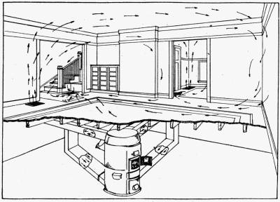
Fig. 27. Circulation of warm air.
58. The Cold-Air Shaft. It is through a cold-air shaft that
the cooler air comes into the furnace. Some furnaces have
this built so that it draws the cooling air from the rooms above
down into the furnace to be heated again. This is an economical
arrangement. Some others draw fresh air from out of
doors into the furnace, letting the cold air from the rooms
above drain into the cellar and out of doors. This is more
expensive, as the air to be heated is usually colder, but it has
the advantage of helping ventilate the rooms by bringing a
constant supply of fresh air.
The cold-air shaft leading from out of doors should have
the outer end covered with wire mesh, and a cloth which
should be washed or renewed often.
Never sweep dirt down a register or cold-air shaft. It
comes back into the room in time. Dust the registers occasionally.
In older heating systems, there was but one large cold-air
shaft to drain the cold air from the rooms above. In more
modern houses, a cold-air shaft is placed in every room that
may be shut off from the others. This does away with the
old difficulty of heating a closed room, for it is as important
that the colder air gets out as that the warm air gets in.
59. Hot-Air Pipes. The hot-air pipes lead from the top
of the jacket about the furnace to the floor above. In most
houses, one pipe goes to each room. This is unnecessary if
the rooms are not closed off, but if they are, they need the
pipe entering the room. To economize with heat and regulate
the amount of air passing up these pipes, there must be
a shutter in them, near the furnace, as well as in the register.
This shutter is placed near the furnace so that no heat passes[61]
into the pipe when not wanted in the room to which it leads.
This saves waste in radiation from the pipe in the cellar.
When a room is not in use, close this damper.
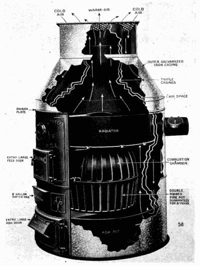
Fig. 28. Pipeless furnace.
Since warmed air will continue to travel upward so long as
it stays warmer than the air above, it is important that the
pipes have a continuous rise thruout their entire length, the
in some parts the rise may have to be only very slight. The[62]
shorter the pipes, the better, for there will be less loss of heat
from radiation on the way to the rooms.
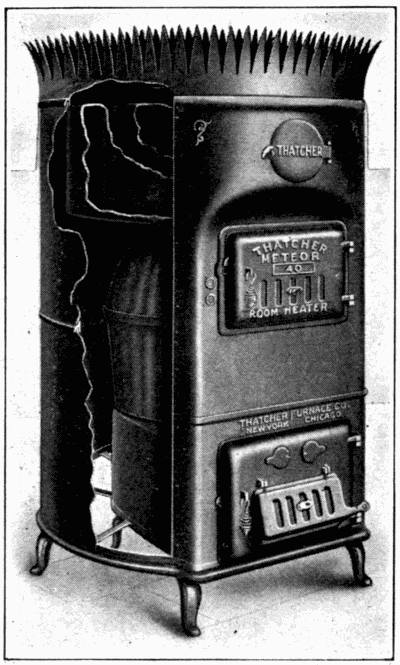
Fig. 29. One-room, hot-air heater.
60. Location of the Furnace. A central location for
the furnace is best because the pipes may be shorter, and this
makes possible a greater elevation per foot of each pipe, so
that the air can flow thru it faster. A central location also
permits a uniform distribution of pipes about the furnace,
which, in turn, produces a more even flow of air to all the
rooms.
The air from the hot register rises to the top of the room,
or, if the way is open, to the top of the house. Here it spreads[63]
over the upper area. As it cools or is displaced by still hotter
air, it falls. When it reaches the floor, it flows down the cold-air
shaft in the floor. If the cold-air shaft is not in the floor,
there may be a layer of colder air there so the room will not
be comfortable.
61. Air. There is a constant change of air in all houses,
due to opening of doors and the fact that walls are not air-tight.
This may not be enough for comfort. If a room is not
heating well, it has been found that opening the window to
change the air in the room, even when the outside air is very
cold, helps in the circulation of air in the room, and so with
the warming of it. It is difficult to warm a room filled with
stagnant air.
62. Pipeless Furnaces. The pipeless furnace works on
the same principle as the one with pipes (Fig. 28). One large
opening above the furnace lets the heat in to some central
room, and from here it circulates into all other rooms not
closed off from the central room. The cold-air shaft may be
around the opening for heated air.
Stoves encased in a metal jacket that operate like hot-air
furnaces (Fig. 29) are used in heating one-room schoolhouses
and other small public buildings.
[64]
CHAPTER VIII
Hot-Water System of Heating
63. Equipment for Hot-Water Heat. The hot-water
system of heating a house consists of a boiler in the basement
or below the level of the lowest radiator. This boiler is designed
to heat water as it circulates through coils over the fire
(Fig. 30). From the boiler, pipes lead to radiators and an expansion
tank, and return pipes bring the cold water back to
the bottom of the boiler (Fig. 31).
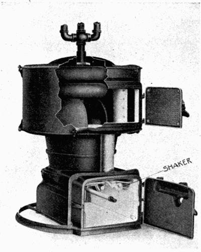
Fig. 30. Garland furnace with hot-water boiler.
The heat from the furnace fire causes the water to circulate
through this system of boiler, pipes, radiators and tank, due to
the fact that hot water is lighter than cold water.
[65]
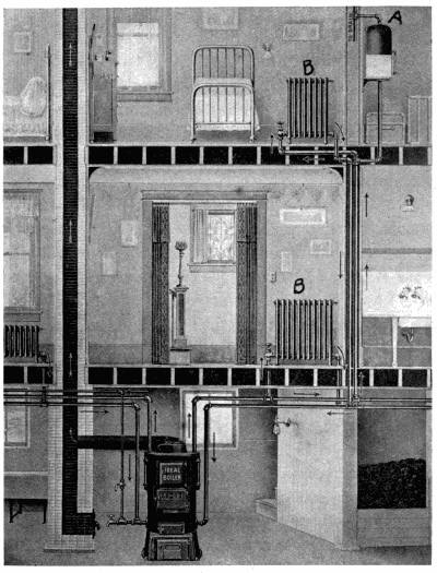
Fig. 31. Hot-water heating system.
64. Heating Unit. The heating unit of a hot-water
system is like any stove consisting of a fire pot and grate.
Some are adjustable so that different kinds of fuel may be[66]
used. A gas burner is sometimes placed in the fire pot and
used for heating a furnace, but this is one of the most wasteful
ways of using gas. A real gas furnace is much more economical.
The fire and heat from the fire circulate around the coils
containing the water. If the coils are not constantly kept
full of water, they will be injured by the heat.
65. The Management of the Fire. When burning
coal, spread the coal all over the surface of the fire in a thin
layer so as not to smother it and thus make it burn with a
smoky flame. Keep the ashes cleaned out from underneath
the fire and around the fire pot. Clean the flues every forty-eight
hours. Soot on the coils is more effective than asbestos
would be in keeping heat from penetrating to the water.
Regulate the fire with the drafts. Open the one below the
fire box to let in air to aid combustion. Open the one found
in most furnace doors a very little. This aids in the combustion
of gases, thus making more economical use of the fuel,
while opening it wider checks the burning of the fire. Broken
and warped doors and drafts let in too much air and destroy the
efficiency of the heater. Open the chimney damper, shown
in Fig. 2, Sec. 3, admitting air to check the draft. Close the
chimney or pipe damper of the type of cook stove shown in
Fig. 2, Sec. 3, to check the draft up the chimney.
66. The Pipes. The pipe carrying the hot water from
the boiler out to the heating system leads to the expansion
tank, the sometimes separate pipes lead from the boiler to a
radiator. Insulate each pipe, except the part in the room to
be heated, with asbestos or some other covering, to keep the
heat in it. Keep the pipes full of water. When they are installed,
see that they are put in so that they gradually rise[67]
upward. If they dip downward at any point, air will collect
at these places and check the circulation of hot water thru
pipes.
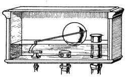
67. Expansion Tank. The expansion tank (A, Fig. 31,
and Fig. 32), placed somewhat higher than the top of the
highest radiator, is fitted with an overflow, for water expands
as it is heated. If the expansion
tank is closed so that the
overflow pipe will not open except
under pressure after the
air in the tank has become
compressed by the expansion
of the water, a higher temperature
in the pipes may be reached, but such a furnace must
be given more careful attention than one with an open expansion
tank. Learn to know the parts of a heating system
and how they operate before trying to manage it.
68. Water. Fill the boiler and radiators full of water,
and add enough more to partly fill the expansion tank. From
time to time, note the height of water in the tank, to know if
more must be added. Do not add water when unnecessary,
as fresh water tends to rust pipes faster than water from
which the carbon dioxide and air have been exhausted. To
note the height of water, read the gage.
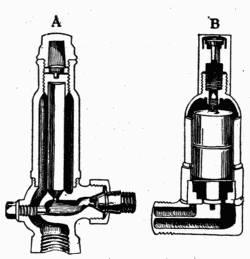
Fig. 33. Vents for radiators.
If there is much sediment in the water used, this must be
drawn off from the bottom of the boiler to prevent its accumulating
there. When this is done, fresh water must be
added to replace the water drawn off. Loss of water from
evaporation must also be replaced. No water should be put
into the system except to replace such loss. Do not draw the[68]
water out of the system, and refill it from time to time. The
practice of changing the water in the furnace rusts it more
than keeping the same water in it all the time.
69. Radiators. Radiators (B, Fig. 31) are made of
rather complicated coils of pipe, so often an accumulation
of air lodges in them. This interferes
with the circulation of the
water and the radiator does not
get hot. There usually is a vent
(A and B, Fig. 33) attached to
each radiator to let out air which
collects there. If a radiator does
not heat well, open the air vent
until the air ceases to flow from it
and water comes; then close it.
Valves should be placed at places where cold water collects
in bad plumbing.
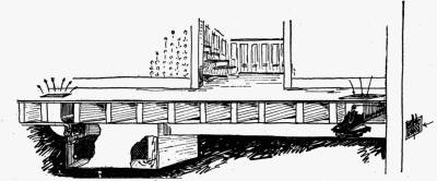
Fig. 34. Radiators under floor.
In very cold weather, do not entirely shut off the valve of
the pipe leading to any radiator, as the circulation of a little
warm water is needed to keep it from freezing. Radiators
may be placed under the floor (Fig. 34) when so desired.
[69]
CHAPTER IX
Steam-Heating Systems
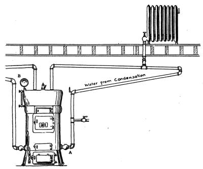
70. Equipment for Steam Heat. A steam-heating
system consists of a boiler, a fire pot, pipes from the boiler
leading to the radiators, and radiators (Fig. 35). On some
systems, return pipes are provided
to carry condensed steam
or water back to the lower part
of the boiler. A safety valve
(Fig. 36) is attached to steam-heating
systems instead of an
expansion tank. This keeps the pressure of the steam in the
boiler from becoming too great, and thereby prevents an explosion.
The pressure gage (B, Fig. 35) must be set, and,
when set, should only be changed by a person understanding
it. Build and manage the fire for a steam boiler the same as[70]
for any stove or furnace. Keep water in the boiler at 212 degrees
Fahrenheit, so steam may form, for without it, the radiators
will not be heated. Small valves are attached to most
steam radiators. Their purpose is to let out air, which accumulates
in the radiator. As soon as the steam begins to
come into the radiator, it forces the
air out of the valve. When it reaches
the valve, the heat in the steam
causes part of the valve to expand
and close the outlet, which is small. When the radiator is
hot, steam should not escape, provided the valves are in good
working order. There is a gage (Fig. 37) furnished with
each boiler which shows how much water is in it.
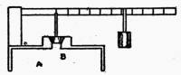
Keep enough water in the boiler to come within certain
lines on the indicator. The top of one of these lines is usually
six or eight inches from the top of the boiler.
There is always some variation in the amount
of water in steam furnaces on account of the
formation and condensation of the steam in
pipes and radiators. See that the boiler is
never empty, but do not put in fresh water
except when necessary.

Fig. 37. Water
gage for
steam
plant.
The space above the water in the boiler is
left for steam. The loss of water from a boiler
in good working order is thru the air valves in
the radiators. If the furnace is properly
managed, very little water should be lost during the course of
a year, so there is little need for adding water.
Some furnaces have two pipes to the radiators. When
steam is shut off from a radiator, the valve leading to the[71]
pipe which carries off the water from condensed steam must
be closed, also, to prevent the pressure of the steam in the
boiler from forcing water from the boiler up this pipe. This
may happen because the pipe draining the water from the radiators
enters the furnace near the bottom of the boiler. The
steam being retained in the furnace presses down on the
water and so may force water up the drain pipe, if it is not
closed, instead of raising the safety valve.
Carelessness of this kind may work much damage, for by
this means all the water from the furnace can be forced up
into the radiators, leaving the boiler empty. This makes it
important that every woman should understand the steam-heating
system in her home.
Some steam-heating systems have a check valve in the pipe
which returns water to the boiler. This valve permits water
to flow thru it in but one direction; that is, toward the boiler.
This prevents a rush of water from the boiler to the radiators.
Steam furnaces, also, are often equipped with another safety-valve
device, which is a plug of metal which melts at a
rather low temperature and is placed in the boiler directly
over the fire. If the water line in the boiler falls low, this
plug melts and steam from the boiler puts out the fire, thus
saving the furnace from damage.
However, melting out the plug makes much work both in
replacing the plug and in cleaning the fire box to rebuild the
fire, so that it should not be depended upon to regulate the
heat in the boiler.
Knocking in steam radiators occurs most often in those
systems using the inlet steam pipe for the return of the water[72]
which has formed as a result of condensation. It is caused by
water accumulating at some point and the steam coming up
the pipe, violently forcing it back into the radiator. This
only reaches a danger point in systems which do not have
pipes of the proper size, or when the pipes do not slope gradually
downward, so that all the water may flow back to the
furnace. On cold days, there will be some knocking in a
steam radiator when it is being heated in the morning. A
two-pipe system, while it is somewhat more expensive, is less
subject to this trouble.
71. Steam Gages. Steam gages (B, Fig. 35) are devices
for indicating the pressure of steam within an inclosure.
They are a kind of spring balance. When the pressure of the
steam increases, it pushes up on the spring, and this turns the
hand of the indicator, which shows the number of pounds of
pressure that the steam is exerting on the inside of the boiler
or container.
72. Safety Valve. A safety valve (Fig. 36 and A, Fig.
38) consists of a small opening to a boiler over which is a
weight. When steam is developed until it makes enough pressure
on the inside of the valve to raise this weight, some of the
steam escapes, thus lowering the pressure on the inside until
the weight falls back into place. Never let anything interfere
with the action of safety valves.
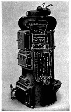
Fig. 38. Heating plant showing
safety valve.
Most safety valves have the weight attached to a lever
which has a movable weight on it so that the position of the
weight on the lever makes a difference in the number of
pounds of pressure required to open the valve. By means of
this device, the temperature of the inside of the boiler can be[73]
kept at one heat or another as desired, since this temperature
increases or decreases with the pressure under which the
steam is held.
Thus, fifteen pounds pressure
means a different temperature
from ten pounds pressure.
Be sure to adjust the weight
for the temperature desired.
Pushing the weight toward the
valve lessens the amount of
pressure needed to open the
valve. There is usually a
steam gage on boilers to indicate
the temperature and
pounds of pressure inside.
When the indicator reaches
the point desired, the safety
valve may be set so that all
steam in excess of the desired
amount will escape. When
this is done, the temperature will be held constant in the
boiler so long as a good fire under it is maintained.
[74]
CHAPTER X
Fireplaces and Heating Stoves
73. Construction of Fireplace. Fireplaces are an enlargement
in the base of a chimney where fire is built. The
upper part of the fireplace is sloped forward, and, in some
cases, a damper is placed in the chimney to regulate the flow
of air upward. The damper should not be so constructed
that it will close entirely, for if it did, the smoke would come
into the room. The fire in the fireplace burns best when the
fuel is put in a grate or on andirons so that air can get under
it and be drawn thru it by the draft of the chimney. A
steady draft makes the combustion of the fuel complete and
thus prevents smoking.
The hearth is made of fireproof material and should be
wide enough to catch all sparks flying from the fire. A screen
is often needed for safety from fire. Do not pile reserved
fuel or put rugs on the hearth.
Fireplaces and chimneys should be built of fireproof brick,
stone or concrete. Have them examined once a year for
cracks, as these make them unsafe. The walls of the chimney
and the fireplace should be thick enough to prevent danger
from fire.
74. Management of Fireplace. The management of a
fireplace is very simple. The draft up the chimney should be
properly regulated so that the fire does not smoke. Sparks
and bits of fuel should not be drawn up the chimney. The
fire should be built so that it is not smothered. Air should
circulate thru the fuel. Keep the ashes cleared away.
[75]
There are some fireplaces which are intended to heat rooms
after the manner of hot-air furnaces. The heat and smoke
from the fire pass upward thru a metal heater, encased by an
air chamber. Much of the heat passes thru the metal, warming
the air in the chamber. This warmed air passes thru
pipes and registers into the rooms, while the smoke finds its
way to the chimney. To complete the circulation of air, the
cold air from the floor passes into the air chamber near the
floor at the sides of the fireplace. Sometimes fresh air from
the outside of the building is mixed with the air in the chamber.
If there is an opening in the floor of the fireplace, a damper
should be put in this opening to regulate the flow of air. The
heater in a fireplace must be kept free from soot and ashes.
If the metal is covered with soot, heat will not readily pass
thru it, and the soot will collect moisture and cause rusting.
One way to keep the heater clean is to regulate the draft up
the chimney so that ashes and bits of burning fuel are not
drawn into it. Also, the fire should be kept burning with a
clear (not smoky) blaze. Soot is unburnt fuel.
75. Operating Heating Stoves. A stove is a device for
holding the fuel and for permitting the heat to pass readily
into the room. In the stove there is space below the fire for
collecting ashes. There is an opening for fresh air to enter
below the fuel, to aid combustion, and a damper above to act
as a check draft when open, a chimney to carry off smoke, and
one or two dampers in the chimney to regulate the draft.
When a fire is being built, close the draft over the fire box
and open the one below; open the damper in the chimney—this
allows the free passage of the air up the chimney.
[76]
76. Care of the Stove. Do not permit a large bed of
ashes to accumulate in the bottom of a stove. A thin layer of
ashes must be kept in the bottom of some wood stoves to
keep the fire away from the metal bottom.
The polish or finish of the stove is a matter of taste. Some
stoves are made of iron, which does not need blacking;
some must be blacked. Blacking keeps them from rusting.
All must be kept free from dust and dirt, as this accumulates
moisture and causes the stove to rust.
Letting the stove get red hot warps it. It should not be
permitted to get so hot.
The grate (Fig. 3) in stoves holds the fuel so that air can
flow up thru it. If the grate is clogged with ashes, this cannot
happen. The grate should be shaken to make the ashes drop
thru. A clean grate is important to the complete combustion
of the fuel. Shaking after glowing coals begin to fall is a
waste of fuel.
When an attempt to shake the grate is made, it may suddenly
refuse to move. In this case, something may have lodged
between its parts, or it may have been shaken from its proper
position. Shaking the stove too hard may displace the grate.
The common remedy for a displaced grate is to let the fire
go out, remove all ashes and cinders, and readjust the grate.
Some kinds of soft coal form "clinkers," and these catch in
the grate. In burning fuel that makes clinkers, shake the
ashes from the fire several times a day. Remove all accumulations
in the fire box daily. Clinkers are made from substances
which melt and recombine, forming a different material
which is quite hard and does not burn. Constant attention
to the fire prevents clinkers from forming in large masses.
[77]
CHAPTER XI
Gas, Electric and Kerosene Heaters
77. Kinds of Gas Heaters. There are several types of
gas heaters—those using an illuminating flame and reflector,
those fitted with a Bunsen burner and an asbestos back, and
those heating water in a device like a radiator. The last two
burn with a blue flame. All gas stoves ought to be fitted with
a flue for discharging the products of combustion.
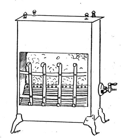
Fig. 39. Gas heater showing air mixer.
78. Bunsen Burner and Asbestos-Back Heater. The
burner is a long pipe punctured with holes extending across
the stove. There is an opening for mixing of air with the gas
at the point where this pipe enters the stove, and a valve to
regulate the flow of gas (Fig. 39).
[78]
79. Lighting Gas Stoves. To light the stove, open the
valve, count three, and apply a lighted match to the burner.
Counting three gives time for the pipe to fill with gas, so that
the fire will not flash back and burn in the air mixer.
80. Care of Gas Stoves. The only care that this stove
needs is to keep it polished so that it will not rust. Keep the
burner clean of dust and soot. Be sure that the valve is entirely
closed when the gas is turned off, and that the pipes fit
tight at all connections so that gas cannot leak into the room.
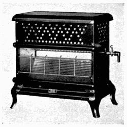
Fig. 40. Reflector gas heater.
81. Illuminating Flame and Bright Metal Reflector
Heaters. These heaters are used with manufactured gas.
They burn with an illuminating
flame since there is no
device for mixing air with the
gas as it enters the stove. The
bright metal reflector not
only makes an attractive
stove, but reflects the heat
out into the room. Some
stoves are made with tips of
aluminum or other non-corrosive
metal over the openings
in the burner (Fig. 40).
Gas logs are a type of gas heaters used in fireplaces (Fig. 41).
82. Gas Radiator Heaters. Gas radiators (Fig. 42) are
another type of gas heater. The radiator is a coil of pipe.
The heating unit is below the coil and works like any other
Bunsen burner. A small amount of water is kept in the
pipes. There is a device attached to the radiator to automatically
adjust the height of the gas fire (A, Fig. 42).
[79]
83. Management of Gas Radiator. Put enough water
in the radiator or coil of pipe to fill it to the depth of one inch.
Keep this amount of water in it at all times.
Light a match, turn on the valve which lets gas flow into
the burner, wait for it to fill with gas, and
touch the match to the burner.
Most of these heaters are fitted with
thermostats.
In about thirty minutes after lighting
the gas, the water will have formed
enough steam inside the radiator to automatically
turn the valve lowering the gas
flame. If the steam pressure falls low, the
thermostat will permit more gas to flow
into the radiator by automatically opening the valve.
There is a safety valve attached to
the side of the radiator which opens if
the automatic device fails to close off
the gas before the steam pressure inside
becomes too great.
84. Kerosene Heaters. Kerosene
heating stoves have burners like
those used on kerosene cook stoves.
(See Chapter III.) Surrounding, or
about, the burner is a jacketed air
space. Here air is heated and rises
to the upper part of the room while
fresh air from the lower part of the room is drawn thru the
jacket. Some heat is also given off by radiation. Fig. 43
shows a picture of an oil heater.
[80]
The burners of these stoves should be cared for the same
way as the ones on cooking stoves. The stove should be kept
polished and free from
dust. This prevents it
from rusting. Wipe off any
kerosene which may accumulate
on the outside, for
it makes an unpleasant
odor.
Take care in moving
kerosene stoves not to jar
the chimney or other parts
of the burner out of place; otherwise the stove will smoke.
When the stove is lighted, turn the burner quite low. The
flame will become higher
as the parts of the stove
become heated.
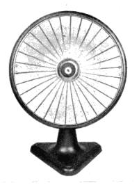
Fig. 44. Electric heater.
85. Electric Heaters.
The electric heaters (Fig. 44)
are composed of one or
more coils of wire thru which
the electric current flows
with difficulty. This heats
the coils so hot that they
glow. A reflector throws
the heat out into the room.
The coil and reflector are
attached to a pedestal.
They are desirable for use
in rooms which are not quite warm enough. Care must be[81]
taken to avoid getting an electric shock from electric heaters,
as from any other electrical appliances. If the stove
seems to be out of order, have it put in order before using.
Take care not to touch a water pipe or gas pipe at the same
time when touching the heater in the bathroom, as there is
a possibility of getting a shock.
86. Acetylene Heaters. Acetylene heaters are similar
to the Bunsen burner and asbestos-back gas heaters. They
are provided also with copper side reflectors. They are used
only in localities where gas or electricity cannot be had.
Questions for Part II
1. What are the essentials in heating a house with a hot-air furnace?
2. How does the "pipeless" furnace differ from the other types?
3. Explain the circulation of water thru a hot-water heating system.
4. What is the purpose of the expansion tank? Where should it be
located?
5. Describe a steam-heating system.
6. What care should be taken in managing a steam-heating system?
7. What precautions should be taken when using an electric
heater?
[82]
PART III
Lighting Devices
CHAPTER XII
Electric Lights
87. Kinds of Electric Lamps in Use. The electric
lamps on the market now are either tungsten (also called
Mazda) or metallized carbon (called gem carbon) lamps. Of
all lighting appliances, electric lamps and systems are most
easily cared for. If properly selected, they make an excellent
light from the standpoint of hygiene. It is important for
every one to know enough about lighting to be able to select
proper kinds and sizes of lamps.
88. Electrical Measurements. A volt is the unit of
electric pressure which compares with the pound as the unit
of water pressure.
An ampere is the unit of electricity flowing thru a wire
which compares to the gallon as the unit of water per minute
flowing thru a pipe.
A watt is the unit of electrical power. It is determined by
multiplying the volts by the amperes.
A kilowatt equals 1000 watts.
A kilowatt hour equals 1000 watt-hours.
A watt-hour is the amount of energy needed by a device
which uses one watt and is operated for one hour. For example,[83]
a 25-watt lamp uses 25 watts, and if it is operated one
hour, it uses 25-watt hours of electricity.
The cost of burning an electric lamp is the number of watts
marked on the lamp multiplied by the hours the lamp is
burned, and then translated into kilowatt hours and multiplied
by the price per kilowatt hour.
89. Carbon Lamps. Few carbon lamps are being made
now, but they may still be obtained in some stores. The carbon
lamp can be distinguished from
Mazda lamps (Fig. 45) by the appearance
of the filament. The carbon
lamp gives about 0.40 candles of light
per watt of electricity consumed. Carbon
lamps burn, making a yellow or
reddish light, and consume fully twice
as much current as Mazda lamps of
the same candle power.
90. Mazda or Tungsten Lamps.
Tungsten lamps are the ones in common
use. They give 0.80 to 1.00 candle
of light to one watt of electricity used. They have a
filament of tungsten and may now be used in any position.
Less electricity is required to bring tungsten to a glowing
white heat than other materials used in lamps.
To compare the brightness of two lamps, do not look at the
filament, but hold pieces of white material like paper at an
equal distance from each lamp and compare the brightness of
the surfaces; or put an opaque object in front of the light and[84]
let a shadow be cast on another object. The brighter light
will cast a heavier shadow.
When substituting a new tungsten lamp for a carbon lamp,
select one about one-half the number of watts, unless more
light is wanted. In houses, it is a common practice to substitute
a 40-watt Mazda for a 50-watt gem carbon lamp, thus
saving ten watts per hour and getting more light.
91. Selecting Lamps for a Room. There are so many
possibilities for the use of electricity in lighting a house, that
it becomes a fine art. When buying lights for a room, consider
(1) the size of the room, (2) the use of the room, and (3)
the color of walls, floors, ceilings, furnishings and decorations.
For lighting purposes, lamps may be obtained ranging from
10 or less to more than 100-candle power.
There are colored, transparent and frosted globes. There
are reflectors and shades of various colors and patterns. To
obtain the same degree of illumination, smaller lamps are
needed in small rooms than in large ones.
92. Effect of Color Schemes Upon Illumination. The
color of the walls and furnishings makes a difference in the
candle power required to give a certain amount of light.
Those colors which absorb the most light require the higher
candle power, and those reflecting the highest per cent of
light require the lower candle power.
The frosted globes absorb some light, they diffuse the rest
of it. They dispense with the annoyance of glare from lamps,
and are useful in places where the full intensity of the lamps
is not required.
The light absorbed by different colors varies considerably,
as shown by the accompanying table:
[85]
TABLE SHOWING ABSORPTION OF LIGHT
| Color |
Percentage
of Light
Absorbed |
| White |
30 |
| Chrome yellow |
38 |
| Orange |
50 |
| Clean pine wood |
55 |
| Yellow paper |
60 |
| Yellow paint (clean) |
60 |
| Light pink paper |
64 |
| Dirty pine wood |
80 |
| Dirty yellow paint |
80 |
| Emerald green paper |
82 |
| Dark brown paper |
87 |
| Vermilion paper |
88 |
| Blue green paper |
88 |
| Cobalt green paper |
88 |
| Deep chocolate paper |
96 |
93. Distribution of Light. Light in rooms for general
use should be distributed as evenly as possible thruout the entire
room. Avoid excessive contrasts of brightness and darkness.
Have the lamps shaded to diffuse the light so that no
one need look directly at the filament. When working by a
light, do not put the lamp very close to the material, as this
produces too strong contrasts of light and dark, or, when
reading, it produces too much reflection from the white parts
of the paper, which is trying on the eyes.
Direct lighting means that the rays from the lamp go directly
into the room (Fig. 45). Indirect lighting means that
the rays are all directed toward a reflecting surface such as the[86]
ceiling (Fig. 46). From here they are reflected, giving an
even amount of light to other parts of the room. When directed
toward the ceiling, they make it the brightest part of
the room.
A semi-indirect light avoids this difficulty (Fig. 47).
In diffused lighting, the lamp is covered, as by frosting, so
that the rays of light are broken up and so scattered that no
direct ray shines into the eyes, and there is no bright spot of
light in the room.
When costs must be limited, certain decorative effects must
be weighed for their value, some being more expensive than
others.
City lighting plants can provide current for any number of
lamps in a house if it is properly wired. If more lamps are
attached than the wiring will carry, and all are turned on, the
fuses will burn out.
Electric plants for private homes (see Sec. 271) usually furnish
current of a different voltage from city electric plants,
so special equipment and lamps must be used with small
plants.
[87]
Inquire of the company who installed the wiring or electric
system, how many lights and other devices can be attached
and for what voltage they should be made.
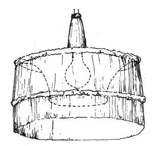
Fig. 47. Semi-indirect light.
[88]
CHAPTER XIII
Gas Light
94. Construction of Mantles. A mantle is a device
made of thread saturated with some fireproof material like a
mixture of thorium and cerium which will glow, giving off a
white light when heated hot. The mantle (A and B, Fig.
48) is placed over the burners of lamps
using liquid or gaseous fuel. The gas
is mixed with air so that it burns
with a blue flame. The blue flame
gives off little light, but it does not
smoke and is much hotter than a
yellow flame. When a mantle is
placed over the blue flame, it is heated
with less fuel consumption than is
required to make a yellow illuminating
flame. The light from the glow
of the mantle is steadier and whiter
than the light from an open flame, so
that it is more hygienic.
Mantles are made in different patterns
so that they may be used on upright and inverted burners.
The inverted mantle throws more light downward than
an upright mantle. This is advantageous in lighting a
room, for most of the light is wanted in the lower part of
the room. Mantles can be used on lamps burning gas, kerosene,[89]
gasoline, alcohol and acetylene if the burners are made
to produce a blue flame. (See Figs. 48 and 52.)
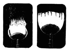
Fig. 48-a. Adjusting gas
light.
95. Care of Mantles. Strong jars and drafts will break
mantles, for they are very fragile. The explosion caused by
burning back when the lamp is being lighted is most destructive
to mantles. To save
mantles, wait until the lamp has
filled with gas before touching the
lighted match to it.
96. Fixtures for Burning
Gas. Gas will burn just as it
escapes from a pipe. The flame
of burning gas is yellow and makes
considerable light. In order to secure more light for the
amount of gas burned, put a tip on the end of the pipe, with
a long, narrow slit in the top to spread
the flame. These are usually lava tips.
Natural gas gives very little light when
burned in an open flame. Always burn it
in mantle lamps. Its heating value is 1000
B.T.U. per cubic foot. When burned in a
well-adjusted mantle lamp, natural gas
will give about 15 candle hours per cubic
foot. The heating value of manufactured
gas is rated at 600 B.T.U. per cubic foot.
It makes a fair light when used in an open
flame burner. The yellow flame of burning
gas makes considerable smoke, even when carefully
adjusted. It gives four times as much light and no smoke
when it is burned in a good mantle lamp.
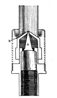
Fig. 49. Bunsen
burner for gas
light.
[90]
In the special burner of the mantle lamp, the gas is mixed
with air so that it will burn with a blue flame (Fig. 49). A
blue flame is not good for lighting, but when a mantle is
placed over the flame, it becomes heated, glowing hot. Since
the mantle is made of a material which gives off a white glow,
it lights the room with a steady light which is far better than
the flickering light of the open flame (Fig. 48-a).
97. Adjustment. See that the ports thru which air is
drawn into the lamp are open as wide
as needed to give a clear, smokeless
flame without firing back. Some
lamps are fitted with a screw beside
the cocks to regulate the amount of
gas flowing into the lamp. It should
be adjusted so that no more gas flows
into the lamp than is needed to get as
bright a glow as possible from the
mantle. Regulate the gas flow by
closing the valve attached to this
screw until the mantle decreases perceptibly
in brightness, and then slowly
opening it until the mantle becomes bright. Gas companies
often adjust lamps for their customers.
98. Care of Lamps. Clean the burners if they become
sooted. Replace mantles if they are broken.
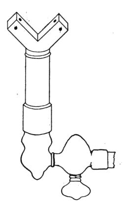
Fig. 50. Open-flame
acetylene burner.
99. Lighting a Gas Light. When lighting a lamp, turn
on the gas, count three, and then light the lamp. Counting
three gives time for the burner to fill with gas and prevents
burning back with an explosion. Mantles are very delicate[91]
and easily broken by jars or strong drafts. Burning back
may break the mantle.
Burning back means that the gas ignites at the opening
where it should be mixing with the air instead of at the tip of
the burner. This happens when the lamp is lighted before it
becomes filled with gas, or when there is too much air mixed
with the gas.
100. Cold-Process Gasoline Gas. It is more economical
to use cold-process gasoline gas with a mantle lamp than
an open-flame burner for lighting.
Be sure to use the burners made
especially for this kind of gas.
The lamps are managed like all
others.
101. Acetylene Lamps. Open-flame
burners are used for acetylene
gas because no mantle burner
has been constructed which
will operate reliably with this rich
gas.
Acetylene gas gives about ten times as much light per cubic
foot as manufactured gas burned in an open flame. The
burners require little care. Sometimes the holes in burners
become stopped, and they should be cleaned out with a fine
pointed instrument like a needle. When they do not work
well, it pays to replace the old tips with new ones.
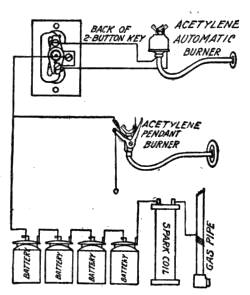
Fig. 50-a. Showing electric
lighting device for acetylene
burner.
Acetylene gas burners are constructed so that a very fine
spray of gas strikes another fine spray, which, when ignited,
makes a broad flame. This flame, which is almost white,
gives off light. The burners appear as illustrated in Fig. 50.
[92]
102. Care of Burners of Acetylene Lamps. Keep the
two holes open. Clean them with a large needle. See that
there are no leaks about the burners or pipes. If these are
found, fill with white lead or some similar substance, and
tighten connections. If this does not suffice, the trouble
should be referred to a plumber. Fig. 50-a shows an acetylene
burner.
Acetylene lamp mantles can be used only with acetylene
which is under high pressure. Therefore, they cannot be
used with all plants. The special burner for mixing air with
the acetylene to make it burn with a blue flame must be used
with the mantle.
[93]
CHAPTER XIV
Kerosene Lamps
103. Construction of Kerosene Lamps. A kerosene
lamp consists of a bowl, a burner, a wick and a chimney.
In the ordinary lamp, the bowl for holding the oil is placed
below the burner (Fig. 51). The wick carries the oil from
the bowl into the burner by
capillary attraction—one end
being in the oil and the other in
the burner.
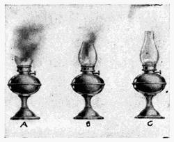
Fig. 51. Lamps and lamp chimneys.
The burner, which has holes
in it to let in air, holds the
wick so that only the oil reaching
the top burns. The area
and shape of the flame depends
upon the form of the top surface
of the wick. The glass chimney is used to cause an
air current thru the burner and to protect the flame from outside
drafts. A screw moves the wick thru the burner. If
the wick is too small, the fire may burn back thru the burner
and ignite the oil in the bowl. It is important that a wick
fit the burner. If the chimney is too short or broken, the
lamp will smoke (A, B, Fig. 51).
104. Management of Kerosene Lamps. When the
lamp smokes, it is wasting fuel. Smoke is incompletely burnt
fuel. The oil in the lamp should be clean. It should never
be mixed with gasoline or other more explosive oils.
Fill the bowl each day the lamp is used to within one-half[94]
inch of the top. A full bowl helps to make a safe lamp.
Put the chimney on the lamp so that it fits in its holder.
Keep it clean and bright. Keep the wick clean and trimmed
evenly. See that it entirely fills the opening thru the burner.
This prevents the fire from burning back down the burner and
igniting the oil in the bowl.
Oil will not pass up a wick which fits too tight. Do not cut
a wick to trim it, but keep the charred part scraped or
brushed off even with the top of the slit in the burner. A
burnt match is useful for this purpose.
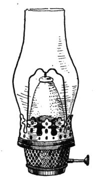
Fig. 52. Mantle for
kerosene lamp.
105. Lighting a Kerosene Lamp. When lighting a
lamp, be sure it is in order and that any
openings to the bowl are closed. Lift
the chimney, turn the screw to raise the
wick about one-eighth inch above the
slit. Touch a lighted match to the wick,
adjust the chimney, and, lastly, move the
wick up or down until it burns clear
and bright without smoking. After the
burner becomes warm, the flame may
grow higher and smoke. Do not leave a
newly-lighted lamp unwatched. After
the lamp is heated and adjusted, it should burn with a flame
of even height.
106. To Extinguish a Lamp. Turn the wick down until
it is slightly below the top of the slit. Do not turn too far.
It will then go out of itself, or a slight puff of air will extinguish
it. This is safer and will smoke the chimney less than
attempting to blow out the full flame.
107. Care of Lamps. Keep the inside and outside of[95]
bowl and chimney clean. Wipe all soot from the burners.
Trim the wick each day the lamp is used. Fill the bowl with
oil to within one-half inch of the top. Get new wicks when
the old ones become dirty.
108. Kerosene Mantle Lamps. Kerosene mantle lamps
(Fig. 52) give three to four times as much light per unit of oil
as the ordinary kerosene lamp. Many mantle lamps on the
market are unreliable. Care, therefore, should be taken to
give the lamp a trial before investing so as to be sure to get a
good one.
The care and lighting of mantle lamps differ so much that
the directions must be furnished by the manufacturer and
should be followed with exactness.
[96]
CHAPTER XV
Alcohol and Gasoline Lamps
109. Classification of Lamps. Since the principle of
operation is the same for most alcohol and gasoline lamps,
they will be considered together.
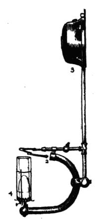
Fig. 53. Gasoline
or alcohol lamp.
These lamps may be divided into two classes—gravity
lamps and pneumatic, or pressure, lamps.
110. Gravity Lamps. Gravity lamps
have the tank elevated above the burner
so that the force of gravity brings the fluid
to the burner. It is usually a little to one
side of the burner so that it cannot become
heated by it. A pipe from the tank leads
downward and either over the chimney or
under the burner, where it will be heated
by the flame of the lamp. When heated,
it changes the gasoline or the alcohol to
gas. The pipe carries the gas on to a
point where it is mixed with air before it
flows into the burner (Fig. 53).
111. Lighting the Gravity Lamp. In order to light
these lamps, the generator must first be heated so as to make
the gas. After this has once been done, the heat of the lamp
keeps the generator hot. As soon as the gas is formed, light
the lamp.
These lamps are furnished with mantles. The flame is blue
and, consequently, gives out very little light, but much heat.[97]
The mantle covering the flame is heated to glowing white
heat and gives off much light of a white color.
112. Pressure Lamps. Pressure lamps (Figs. 54 and
55) have a strong tank which holds air and fuel, whether alcohol
or gasoline. Air is pumped into the tank so that it presses
on the fuel with force enough
to push the fuel up the pipe
leading from the bottom of the tank to the generator. The
air cannot get into the pipe so long as there is fuel which is
heavier than air in the tank, because the pipe which leads to
the burner starts from the bottom of the tank.
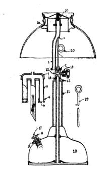
Fig. 54. Details of gasoline
lamp.
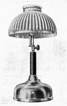
Fig. 55. Pneumatic gasoline
lamp.
————
The generator for changing the liquid fuel to gas is placed
between the burners of the lamp, of which there are usually
two. After the generator has been heated, the lighted lamps
keep the generator hot. The gas being very light, continues[98]
to rise. It passes thru a place where it is mixed with air, and
goes on into the burner, where it is ignited. If the lamp
burns low, more air must be pumped into the tank to force up
the gasoline or alcohol. When all the fluid has been burned,
the lamp will go out, since, then, only the air which is under
pressure in the tank will be coming into the burner.
Extinguish the lamp by turning off the supply of fuel to the
generator. To light these lamps, first heat the generator, as
directed for the particular lamp in use, and then light the
burners. Detailed directions cannot be given here, as they
differ with different lamps.
113. Gasoline Lamps with Wicks. There are some
gasoline lamps made with wicks which help conduct the oil
into the burner, where it is changed to gas by the heat from
the lamp, mixed with air and burned in a mantle. The flame,
from a mixture of alcohol or gasoline and air, is blue and gives
off little light, but much heat. It is used with a mantle.
114. Alcohol Lamps with Wicks. The wick of one
type of alcohol lamp conducts the alcohol up thru a round
tube which it completely fills. The tube prevents the fire
from burning down into the bowl of the lamp. Alcohol
makes a very hot and almost smokeless flame, even when
little air is present. The mantle is put over the flame, and,
when heated, gives a good light. Other ordinary fuels cannot
be used on so simple a lamp because they would smoke the
mantle.
115. Lighting Alcohol or Gasoline Lamps. Heat the
conducting pipe at the point where the fuel is to be changed to
gas. (Directions for this come with each lamp, and they differ
considerably.) After being heated sufficiently, the valve[99]
leading to the burner is opened and the burner lighted with a
match or torch. Use clean gasoline for these lamps, unmixed
with water or other substances.
Questions for Part III
1. Are there any differences in the electric light globes on the market?
If so, in what ways do they differ? How do these differences affect the
lighting power of the globes?
2. What influence has the size and decoration of the room on the
brilliancy of light from a given lamp?
3. How should the light in a living-room be distributed?
4. What are the differences in direct, semi-direct and indirect lighting?
5. What is the purpose of a mantle for a gas or kerosene lamp?
6. What is the difference in burners to be used with and without
mantles?
7. How is the light from a lamp measured?
8. Which lamp gives the greatest candle power of light for the
amount of fuel used—the one with or the one without a mantle?
[100]
PART IV
Cooling Devices
CHAPTER XVI
Refrigerators
116. Principles of Refrigeration. Refrigerators (Fig.
56) are designed to prevent the rapid spoiling of food by keeping
it too cool for the rapid growth of bacteria. They vary
considerably in their efficiency, according to their construction
and to the way in which they are managed. To preserve
food and to save ice, the housewife must understand her refrigerator,
and she must choose a good one. There is as much
difference in the efficiency with which housewives manage
their refrigerators as there are differences in refrigerators.
[101]
A series of experiments were conducted with a number of
different makes of refrigerators. When the outside temperature
was between 80 and 90 degrees Fahrenheit, and when the
refrigerators were kept full of ice, it was found that the temperatures
in different refrigerators varied between 45 and 60
degrees Fahrenheit. When the refrigerators were only partly
full of ice, their temperatures rose several degrees.
The refrigerators which held a temperature of 45 degrees
when filled with ice, or with 100 pounds, used 25 pounds of ice
each in three days, while in the same three days, the ones
which could maintain only a temperature as low as 65 degrees,
used 50 pounds each. The warmer the inside of a refrigerator,
the faster the ice melts.
In general, a refrigerator which maintains a low temperature
is cheapest to operate. The refrigerator should be kept
full of ice exposed so that it comes in contact with the air circulating
within the refrigerator. The refrigerator which does
not hold a low temperature will not only use more ice, but be
less efficient in keeping food.
117. The Construction of Refrigerators. The construction
of a refrigerator should be such that it may be kept
clean. There should be no cracks and corners to catch dirt
and make breeding places for molds and bacteria.
118. Lining Refrigerators. The best linings for refrigerators
are porcelain, porcelain enamel, or glass for the more
expensive ones, and galvanized iron or zinc for the less expensive
ones. The shelves are usually made of heavy wire or
of bent metal. The latter should be constructed so that they
can be thoroly cleaned.
[102]
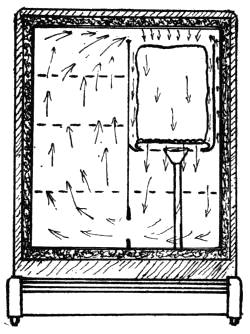
Fig. 57. Diagram showing circulation
in a refrigerator.
119. Insulation of Refrigerators. The more complete
the insulation of a refrigerator, the more efficient it will be.
Different kinds of material, as well as dead-air spaces, are
used for this purpose. The top,
as well as the bottom, must be
insulated. Materials which are
likely to crack or settle down
and leave uninsulated spaces
should not be used. Because
sawdust settles, it is not satisfactory.
There are felts, papers
and other materials which are
good. If the refrigerator is not
water-tight and the insulating
material absorbs water, it will
lose its efficiency for insulation.
120. Circulation in Refrigerators.
The better the circulation in a refrigerator,
the more efficient it will be. The air in the refrigerator must
be free to circulate over the ice. As it cools, it should drop
to the bottom of the ice box. When it warms, it will rise and
be displaced by fresh falling cold air. It should be free to rise
to the top of the refrigerator and from there pass into the ice
chamber and over the ice to be cooled again (Fig. 57). When
the ice always melts unevenly and in the same relative
place—that is, more on the side or bottom—it indicates
poor circulation in the refrigerator.
121. Drip from Melting Ice. There should be a pan
under the ice to catch the drip from the melting ice, and a
drip pipe to carry it out of the refrigerator (Fig. 57). If the[103]
drip pipe passes into a pan set under the refrigerator, the pan
should be emptied so that it will not overflow. The water in
the pan should not be allowed to become stagnant.
If this pipe passes to a drain, it should not be attached to
the drain, but drip into it. The small amount of fresh air passing
up the drip pipe from the room is advantageous. Because
some air does flow thru here, the drip pipe and the drain pipe
must be clean and free from gases and odors.
The drip pipe should be straight and free from places in
which dirt may collect. It must be removable, so that it can
be cleaned. The doors of the refrigerator must shut so tightly
that frost or dew will not form about their edges on a hot day.
122. Arrangement of Food in the Ice Box. Ice boxes
are usually cooler at the bottom than at the top. Do not put
food in the ice chamber because this necessitates opening the
door and wastes ice. Do not put papers or flat boxes on the
shelves which will interfere with the circulation of air in the
refrigerator.
123. Filling and Care of the Ice Box. The housewife
must open the doors of the ice box as seldom as possible, and
close them quickly. Do not cut off the circulation of air
from the ice by wrapping it in a blanket or newspapers. It
cannot do its work then. The ice box is kept cold by the
gradual melting of the ice. The ice melts fastest as the temperature
of the ice box rises. Covering the ice may keep it
from melting, but it will also allow the refrigerator to get
warm, and so, whatever is gained in saving ice at first, will be
lost at the higher temperature and in cooling the box again.
Steady melting does the most good.
[104]
The shelves and drain pipe should be removable, and these
and the refrigerator should be washed and thoroly scalded
once in every two weeks.
There is a saving in planning to open the refrigerator as
little as possible. The filling of the ice box with a large piece
of ice two or three times a week, rather than with a small
piece every day, is more economical.
[105]
CHAPTER XVII
Iceless Refrigerators; Water Coolers
124. Comparative Efficiency of Iceless Refrigerators.
In some localities, where it is difficult to get ice often enough
to pay for having a refrigerator, other devices have to be depended
upon for keeping food cool. Except when cold running
water can be used in coolers, they do
not take the place of refrigerators, because
they cannot maintain the low temperature
of a good refrigerator. As a rule,
the best of the makeshifts are about on
a par with the poorer refrigerators. They
are very useful in emergencies.
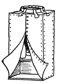
Fig. 58. Iceless
refrigerator.
125. Iceless Refrigerator. One of
these devices is called the iceless refrigerator
(Fig. 58). It depends upon the evaporation
of water to make it cool. Water will evaporate
sufficiently fast to cool a refrigerator enough to be of value
only in a dry, hot, breezy place. Under the most ideal condition,
an iceless refrigerator may hold as low a temperature
as 65 degrees Fahrenheit, when the thermometer is registering
above 90 degrees.
This refrigerator consists of a cloth-covered frame and a
device for keeping the cloth moistened with fresh water.
Since wind or a good circulation of air helps in the evaporation
of water, the iceless refrigerator must be placed where[106]
breezes may reach it, and it should be anchored so that it will
not blow away.
An iceless refrigerator may be made from a rectangular
frame of wood, to which heavy canton flannel is buttoned or
tacked. On the top of this should be placed a pan of water
with strips of cloth extending from the water to the covering
of the frame. This will conduct the water from the pan out
onto the cloth. The number of strips of cloth regulate the
rapidity with which the water is carried
to the sides of the refrigerator.
The food is set inside (Fig. 58.) The
refrigerator should be placed in a shady
spot where the breezes can strike it.
Iceless refrigerators must be kept clean,
and the covering of cloth should be
washed occasionally.
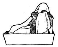
Fig. 59. Device for
cooling food.
Some iceless refrigerators are enclosed in a chimney-like
closet built on the house, the cold air coming in at the bottom
and being drawn upward by the natural draft of the
chimney-like structures. This draft hastens the evaporation
of the water. Such refrigerators are expensive and less satisfactory
than ice ones.
126. Small Cooler. A few things may be kept cool,
like a bottle of milk and a small dish of butter, by setting
them in a shallow pan of water and covering them with a flannel
cloth which comes down into the water and so remains
moist (Fig. 59). The evaporation of the water from the flannel
cools the food somewhat below the temperature of the
surrounding air.
127. Covered Pail. Another device is a metal pail (Fig.[107]
60) covered with a heavy layer of cloth and a pan set on top of
the cover. Into the pan is put some water and strips of cloth
to conduct out the water. This may be hung in the kitchen
window if it is shaded. The cover and the
strips must be secured so that they will not
blow off.
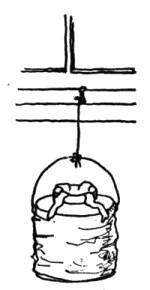
Fig. 60. Covered
pail for
cooling food.
128. Unglazed Earthenware. Unglazed
earthenware pitchers and jugs make
excellent water coolers. The water is put in
them, and, as the container is porous, a small
amount filters thru the earthenware, and, as
it reaches the surface and air, it evaporates,
cooling the remaining water.
129. Cooling with Running Water.
A very little stream of water from a faucet
will cool the baby's milk and keep it from souring. The
bottle should be set in a pan of water which is constantly
renewed by the small stream running
from the faucet. (Fig. 61.) This
method of cooling should be used only
in homes supplied with water from a
spring or in an emergency. Under
most circumstances, it is too extravagant
a method of keeping food to be
recommended. In cities it should be
prohibited because it might cause too
great a drain on the city water supply.
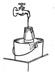
Fig. 61. Cooling with
running water.
A larger device used for cooling milk is a tank of running
water (Figs. 61-a-b). The water flowing thru this tank
commonly flows into another tank used for the watering of[108]
stock. Cans with inverted covers like those illustrated are
waterproof, because the air is caught inside them so that it
cannot get out for the water to replace it. It does not require
a large stream of water to renew
that in the tank and
keep it cool. The efficiency
of this device depends entirely
upon having a supply
of cold water available.
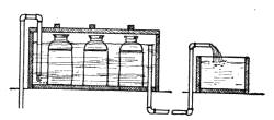
Fig. 61-a. Cross-section of
cooling tank.
130. Refrigerating Plants. Refrigerating plants are
sometimes installed in private dwellings. These consist of a
motor and a machine for compressing gas, a chamber which
is to be cooled, and sometimes coils of pipe containing brine.
When the gas—for example, ammonia
or carbon dioxide—is compressed,
it heats the pump which compresses
it. That is, when a liquid or
gas is being compressed, it gives up
heat. When a liquid or gas expands, it
takes heat from somewhere. In refrigerating
plants, the expanding gas is
made to take the heat either directly
from the refrigerator or storeroom, or from brine which is
then used for cooling the refrigerator or room. Refrigerating
plants require the same care as pumps, motors and refrigerators.
131. Water Coolers. Since ice is not always pure, it
is necessary to use cooling devices which do not permit it to
come into direct contact with the water. One type of water
cooler consists of a can set in an ice box with a pipe leading[109]
to the outside so that the box does not have to be opened
every time that water is wanted (Fig. 62). This can should
be made so that it may be removed, washed and scalded.
Another cooler consists of a tank or water bottle placed on
the outside of a refrigerator or box of ice with a pipe leading
thru the refrigerator or box of ice (Fig. 63). The water flowing
thru the pipe is cooled. The pipe ends at the outside of
the ice box with a faucet to let out the water. This cooler
cools only the water flowing into the pipe instead of the entire
tank of water.
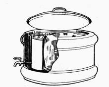
Fig. 62. Water cooler containing
water tank.
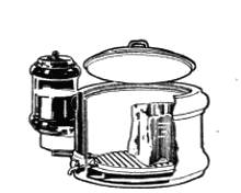
Fig. 63. Sectional view of
water cooler.
————
132. Care of Water Coolers. Put only clean, pure
water into the coolers, and keep them clean by flushing them
out occasionally with boiling water.
[110]
CHAPTER XVIII
Fans and Ventilators
133. Selecting a Fan. With the coming of electricity
into the home, fans have become practical home devices. Do
not buy a fan or other electrical device without ascertaining
whether the current is direct or alternating, and what voltage
is needed to run it. Most city homes are now supplied with
current ranging between 105 and 115 volts, so most fans are
made for that. Fans will run on a small wire like that used
for lighting.
————
134. The Construction of the Fan in Common Use.
A motor turns the fan. There is a regulator on some fans, so
that they can be run at different rates of speed. Oil cups are
important parts of fans. When a new fan is purchased, these
cups are full of oil. The oil will last for many months, but if
an old fan heats and sparks while being run, have an electrician
examine it to see if all the parts are in order and there[111]
is a supply of oil. Figs. 64, 65 and 66 show types of fans in
common use.
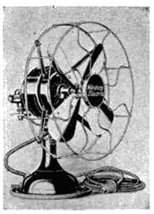
Fig. 66. Movable electric fan.
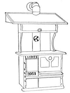
Fig. 67. Stove ventilator.
————
135. Ventilator. A hood (Fig. 67) with a pipe leading
into the chimney, placed over a cook stove, will conduct hot
air and steam up the chimney. This is due to the fact that
warm air rises and cold air comes in to take its place. An
open skylight over a cook stove, also, makes an excellent ventilator
and cooling device for kitchens.
Questions for Part IV
1. How may refrigerators be judged for efficiency?
2. What are the essentials of a good refrigerator?
3. How is an iceless refrigerator cooled? Under what conditions is
it useful?
4. What may be the matter with an electric fan when it heats and
sparks?
[112]
PART V
Water Supply and Sewage Disposal.
CHAPTER XIX
Pumps and Water Filters
136. Suction Pumps. A pump is a device for lifting
water. The pumps in common use work on the principle
that water which is under the pressure of air will rise to fill a
vacuum or a partial vacuum. The pump is composed of a
combination of valves and a piston for forcing the air out of
the pipe to allow the water from below to be forced into it. A
valve catches the water as it starts to flow back. The weight
of the water holds the valve closed.
An outlet above the piston permits the water to flow into a
tank or sink when the piston is again lifted to make a new
vacuum and draw more water (Fig. 68).
137. Care of Pumps. The leather or material forming
the piston must be kept moist, or it will shrink and leak.
When it becomes worn and old, it must be renewed. It is not
a difficult task to put new packing on a small suction pump.
To do this, remove the pin attaching the piston to the handle.
Lift out the piston, unscrew the bolt which holds the leather
packing in place; put on the new packing, and replace the
bolt, piston and pin.
Always pump with a regular, even stroke—a jerky one
tends to wear the working parts of the pump.
The cylinder and pipe containing water must not be allowed
to freeze. There is usually a plug in the pipe which[113]
may be removed to let out the water when there is danger of
freezing. A cracked cylinder or pipe will leak air and not
raise water.
Keep the bearings for the handle well oiled. When the
pump gets old, the cylinder
becomes worn and leaks. It
can sometimes be replaced
with a new cylinder, or more
packing must be put on the
piston.
138. Force Pumps. Force pumps are used on deep wells
and in forcing water into storage tanks. They should be kept
oiled; they should be operated with an even stroke, and the
packing in them should be renewed if they leak air. In force
pumps, the valves differ in their arrangement from suction
pumps (Fig. 69).
139. Compressed-Air Pumps. Compressed-air pumps
consist of a tank for storing the compressed air—a pump to
force air into the tank and cylinders equipped with valves.[114]
These act automatically. Whenever an outlet pipe is opened,
the extra pressure of air from the storage tank raises the water
from the well or cistern (Fig. 70). Air should be kept in the
pressure tank.
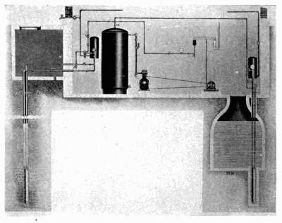
Fig. 70. Compressed-air pump system.
When this arrangement is used, open and close faucets
slowly, not with a jerk. Fig. 70-a shows plumbing where
such a system is used.
140. Water Filters. Water filters are devices for straining
minute particles out of water. They are made of sand,
charcoal or porcelain, kisselguhr and other materials. They
are without value unless they are kept clean. A dirty filter is
worse than none. Almost the only way to clean them is to
sterilize them or put new material in them. Only with expert
care can filters be made effective for removing disease
germs. A dirty filter may prove a menace. Filters are valuable
for removing coarse dirt from the water.
[115]
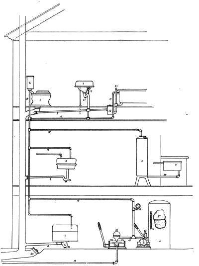
Fig. 70-a. System of plumbing with compressed-air tank.
[116]
Filters on faucets should be cleaned or renewed every day.
Large filters for rain water should be renewed every few
months.
[117]
CHAPTER XX
Pressure Tanks; Plumbing Fixtures
141. Pressure Tanks. A pressure tank is a device for
storing water under pressure. It is usually placed in the
basement of dwelling houses.
142. Construction of the Pressure Tank. The tank
is tight and strong, so that it will hold air and water under
pressure. The tank originally has some air in it. When the
water is pumped in, the air not being able to escape, is compressed.
When there is a chance for water to escape from the
tank which is connected to water pipes, the pressure of the
compressed air on the water forces it to upstairs rooms and
other points. To this tank is attached a pressure gage
which indicates the amount of pressure; or, in other words,
the amount of water in the tank, for when the water gets low,
the pressure is reduced unless the air has escaped. A glass
gage shows the height of water. Provision is made to let
some air into the tank, for otherwise it may in time be all
forced out of the tank or absorbed by the water. The water
in a pressure tank may be used to pump water from a cistern
into another tank.
143. Care of Pressure Tanks. A pressure tank must
not be pumped up to the extent that the pressure becomes
greater than the strength of the tank. A safety valve is used
in controlling the pressure.
144. Hot-Water Kitchen Tank. A force pump is generally
used for pumping water into kitchen tanks, except[118]
when water from another tank, such as a city reservoir, flows
into it.

Fig. 71. Instantaneous water
heater.
145. Instantaneous Water Heaters. The instantaneous
water heater (Fig. 71) is
a device which heats water on
its way to the outlet. It is
composed of a heating unit and
piping connected to the outlet
pipes. In this type of heater,
the pipes must always be kept
full of water, and some device
should be attached (Fig. 72)
to the heater which will lower
the heat as soon as, or
before, the water reaches boiling temperature. This will
prevent steam from forming, which might injure the system.
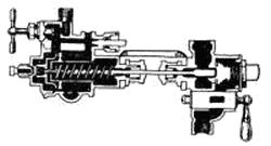
Fig. 72. Device for heating
water automatically.
146. Heaters for Tanks. Hot water is lighter than
cold. A pipe from the bottom of the tank leads into the
heater, passes thru the heating coils and up into the top of the
tank (Figs. 73 and 74). Water from the tank circulates thru
this pipe as the hot water rises and the cold water falls in the
tank. As the heater is located on a level with the bottom of
the tank, cold water seeking this level flows into the pipe and
becomes heated (Fig. 76).
[119]
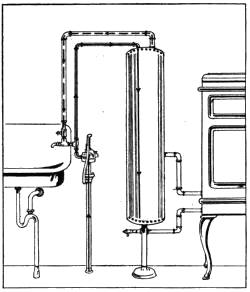
Fig. 73. Force pump and boiler.
A booster is a device which keeps the water hot up to the
faucet (Fig. 75). If there is a pilot on a gas water heater,
be sure to use it. The burners should be cared for in the
same way as on other heaters using the same fuel. Keep the
tank full of water and the
water free to circulate
thru the pipes. Air-tight
tanks may become so hot
that steam is formed in
large amounts. Tanks
which are not connected
with city water pipes may
be fitted with safety valves
which open when the pressure
of steam inside the
tank reaches a certain
point, which is below the
danger point.
Should the pipes or tank freeze, do not start the fire in the
heater, but thaw the pipes with applications of hot water or
other means until the water can circulate in them.
Electric heaters are usually incased in a waterproof covering
and put in the center of the tank. Small electric heaters
are in use for heating a glass or other small amount of water.
These are called immersion heaters.
147. The Elevated Water Tank. In rural homes, water
is sometimes stored in an elevated tank. This is usually
placed in the attic. It is frequently filled by means of a force
pump connected with a windmill or gasoline engine. If there
is no overflow to this tank, which there should be, it must be[120]
watched when being filled to prevent it from overflowing. It
may be fitted with an automatic device similar to those used
on the expansion tanks of hot-water furnaces or tanks to
water closets for regulating the inflow of water.
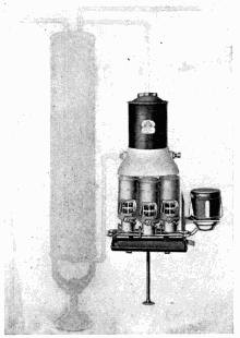
Fig. 74. Water heater and tank.
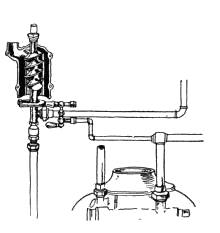
Fig. 75. Booster for hot water.
148. Faucets. Faucets are made in different patterns,
but they need practically the same care (Fig. 77). The leather,
or rubber, washer in a faucet must be renewed when it leaks.
To renew the washer, unscrew the cap from the faucet. Remove
the valve. Take off the ring of packing. Replace
with a new ring, and put the faucet together again. The only
tools needed for this repair work are a wrench and a screwdriver.
Shut off the water from the pipe to the faucet before
beginning to repair a leaking faucet.
[121]
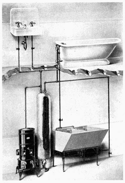
Fig. 76. Water tank and heater.
[122]
149. Valves. Valves are constructed much like faucets.
They, too, sometimes need repacking. Follow the directions
for repacking of faucet (Fig. 78).
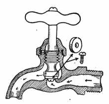
Fig. 77. Faucet showing
parts.
————
150. Overflows. Keep overflows clean. When the plug
and overflow are combined, as they sometimes are, lift out
the cylinder forming the plug and overflow and wash it.
When it fails to hold water in the tub or basin, it may need[123]
a new washer on the lower part. This may be replaced very
easily. Fig. 79 shows one type of overflow.
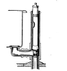
Fig. 79. Cross-section of overflow
on bath-tub.
————
It is more difficult to keep other overflows clean. They
may be flushed or cleaned with a brush attached to a wire.
151. Traps for Bath Tubs and Basins. Dirt and
slime collects in traps. Clean them frequently. Always
leave clean water in the traps of bathroom fixtures and
sinks. Only matter quickly soluble in water should pass
into drain pipes. Keep matches, hair, sweepings, rags, fruit
skins and stones out of the fixtures.
If the drain from a basin, sink or tub fails to carry away the
water, the stoppage may be removed with a small plumber's
pump (Fig. 80). This is a small rubber cone-like device
which is placed over the outlet to the drain and moved up and
down so that it sucks air, water and whatever may be movable
up the pipe.
[124]
CHAPTER XXI
Cesspools, Septic Tanks and City Sewer Systems
152. Relative Value of Cesspool and Septic Tank.
Sewer pipes for private water systems usually drain into cesspools
or septic tanks (Figs. 81, and 81-a). The waste goes thru
a process of decomposition before passing out into the soil.
Sewage should both liquify and oxidize before entering into
the soil. Oxidation purifies liquid sewage so that it is not
contaminating. If oxidation is not brought about in the
cesspool or septic tank, sewage, which is fresh, should be run
onto the surface of the ground where the air and bacteria for
oxidation can be found. Cesspools are not as good as septic
tanks because there is not the surety of sewage being oxidized
in them, as there is in the septic tank. They lack oxidizing
chambers.
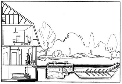
Fig. 81. Septic tank and tile.
[125]
Unoxidized liquid sewage being in a condition to flow readily
thru the earth, is more dangerous than fresh sewage because
it is more likely to seep into wells.
153. Construction of the Septic Tank. The septic
tank is composed of two chambers—one the liquefying chamber
and the other the oxidizing
chamber. Both are
water-tight (Fig. 82). The
fresh sewage comes into
the liquefying chamber
thru a pipe placed near the
top of the tank. Here it
stands and liquefies, which
is a process of decomposition.
The solids fall to the
bottom as they come into
this chamber, and the
liquid formed rises to the
top and flows into the oxidizing
chamber (B, Fig. 82), when it reaches a point a little below
the height of the inlet pipe. It either does this by flowing
over a partition or thru a pipe leading from one compartment
to the other.
The second compartment is usually slightly smaller than
the first. Here the sewage is held until the process of oxidation
takes place, which renders it less dangerous. When the
sewage in the second chamber reaches a certain height, it
siphons out into a tile which distributes it over a plot of
ground (Fig. 81).
Various kinds of siphons are used, the important feature of[126]
them being that they are constructed so that they drain the
tank often enough to remove the oxidized sewage and not so
often as to remove it before it has become oxidized.
154. The Size of Tank. Because the liquid must be
drained from the tank at certain intervals, it is important that
the size of the tank be adapted to the amount of waste it
will receive.
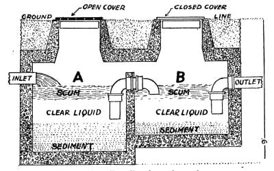
Fig. 82. Details of septic tank.
Septic tanks are kept warm by the heat generated in the
oxidizing process, which is simply slow burning of the waste,
so that they rarely freeze in winter.
Run waste water from the kitchen sink and laundry tubs
into a catch basin to collect the grease from the water, as
grease or oil on the surface of the sewage of a tank will stop
the action of the microbes in the tank by smothering them.
When too much grease does get into it, the tank must be
thoroly cleaned.
Do not use lye, chloride of lime, carbolic acid and other
chemicals in drains and septic tanks. Disinfectants of this[127]
type put into pipes leading to a septic tank will kill the useful
bacteria which decompose the sewage.
Use clear boiling water to clean the pipes. This will be
cooled by the time it reaches the tank so that it will not kill
the useful bacteria.
Insoluble mineral matter gradually accumulates in septic
tanks, so that they must be cleaned once every few years.
Care will postpone the times for cleaning.
Do not wash vegetables with much earth adhering to them
in sinks leading to cesspools or septic tanks. Shake or rinse
off the dirt before washing them.
155. Disposal of Waste in Cities. In some cities,
householders are required by law to have catch basins connected
to their sewer systems to remove leaves and dirt from
storm water and grease from kitchen sinks and laundry tubs.
The laws of other cities forbid the use of catch basins, but urge
householders to help care for the city sewer system by not
putting grease into sewer pipes.
Strong chemicals should not be put into the pipes. Use
only boiling water in cleaning pipes. Do not wash vegetables
on which there is much loose dirt in sinks.
[128]
CHAPTER XXII
Water Closets
156. Construction of Water Closets. The water closet
is a device for the disposal of excrement. The closet includes
a tank of water for flushing the waste from the bowl to the
sewer or waste pipe. Between the bowl and the waste pipe is
a device called a trap which holds water and seals the end of
the waste pipe so that gases from the sewer or the septic tank
cannot come into the house. (Fig. 83-a.)
The bowl of the newer models of water closets have the trap
as a part of the bowl, which saves joints and connections
likely to catch dirt and stop up the trap (Fig. 83). The
water coming from the flushing tank is carried around the
bowl so that it is flushed clean by the swift-flowing water.
When the water reaches the bottom of the bowl, it rushes
upward a few inches before it can turn downward to the
waste pipe. This it does while flowing rapidly and cleansing
the bowl; when the tank empties, water collects in the bowl to
the level, where it can flow down the waste pipe (Fig. 83). As
soon as all the water above this level has gone down the pipe,
the remainder stays in the bowl, forming the seal until the
next time the bowl is flushed. Fig. 83-a shows two kinds of
traps.
If water flows at too rapid a rate thru the trap of the bowl,
as in cases when there is too much pressure on the water or
the tank is set too high so that gravity gives it too much force,
or if an excessive suction is produced in the drain pipe, all the
water may run out of the bowl, leaving the trap unsealed.[129]
The remedy for this is a change in the flushing tank or in its
position.
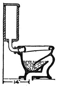
Fig. 83. Section
of water closet.
157. Siphoning the Trap. If rags or shreds of material
are dropped into the bowl and lodge in the trap, only a part of
them going over into the waste pipe, they
may siphon the water, sealing the trap, over
into the waste pipe. There was more difficulty
of this sort with traps of older models
than with the newer types. Always leave
clean water in the trap.
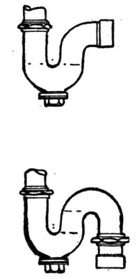
Fig. 83-a. Types
of traps.
158. The Flushing Tank.
The flushing tank (Fig. 84) is
a reservoir to hold sufficient
water to cleanse the bowl. In one type of
tank, water is retained in the tank by a plug
held in place by the weight of the water in the
tank. By a lever on the outside of the tank,
this plug is lifted when the bowl is to be flushed,
and it stays open until all the water flows
out of the tank. When the water has all left
the tank, the plug falls back into the hole and fresh water
flowing into the tank holds it in place, as there is nothing in
the pipe below to make it float upward.
Working at the same time with the plug is a valve in the
water supply pipe, attached to a large hollow float. The
valve opens as the water flows out of the tank, and closes as
the tank is filled. This valve is operated by the float floating
on the surface of the water. As the water flows out of the
tank, the float falls, opening the valve and letting in water.
As the tank fills, the float rises to the top of the tank and[130]
shuts off the valve. If the float catches so that it fails to rise
and fall, or becomes disconnected from the valve, it will not
operate the valve. There is an overflow pipe in the tank
which carries off all water rising above a certain level in the
tank. This prevents the tank from overflowing when the
valve fails to turn.
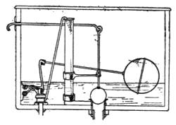
Fig. 84. Diagram of
flushing tank.
159. Repairing the Flushing Tank. When the water
continues to flow into the tank, take off the cover of the tank
and examine the valve and ball to see
why they are not working properly. If
disconnected or caught, remedy the
trouble. If the plug fails to stop the
flow of water out of the tank, water will
also continue to flow into the tank. To
remedy this temporarily, push the plug
down over the outlet and also note the reason why it has not
fallen back automatically. If worn, it may have to be replaced
with a new one.
There should be a valve to close the pipe to the tank. With
this valve, much water can be saved in time of trouble, and
greater convenience may be had in remedying difficulties
with the devices inside the tank.
Questions for Part V
1. How does a pump lift water from a well?
2. How do pumps differ in construction?
3. What care should be given a pump?
4. When is a water filter useful? When dangerous?
5. What is a pressure tank? How does it operate?
6. Describe two kinds of water heaters. What precautions should
be taken with each kind of heater?
[131]
7. Describe a water faucet. Try to replace an old washer with a
new one.
8. Have you ever cleaned the overflow to a tub or basin? Should
they be cleaned?
9. What are traps? What may cause them to fail to work?
10. How would you select a good trap? How would you clean it?
11. Describe the construction of a septic tank. What is the action
that takes place in a septic tank? What care should be given to it?
12. Examine the tank to a water closet. How does it operate?
[132]
PART VI
Laundry Equipment.
CHAPTER XXIII
Washing Machines
160. Kinds of Washing Machines. Washing machines
are tools to help remove dirt from clothes either by friction or
by forcing water thru them. They are known by such names
as suction, cylinder, rotary, oscillating, locomotive and centrifugal
machines. These names are used differently by various
authorities.
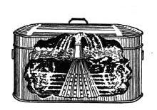
Fig. 85. Washer to place in boiler.
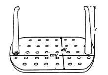
Fig. 86.Another type of
washer for boiler.
————
Washing machines may be attached to any kind of motor,
or they may be manipulated by hand.
161. Suction Machines. The suction machines are
made to force water thru the clothes (Figs. 85 and 86). Some
are operated by hand, some by mechanical power, and some
are funnel-shaped devices to be placed in boilers.
Hand or mechanical suction machines have cones or funnels
which are pushed down onto the clothes and then suddenly
lifted, causing suction which draws out the dirt previously[133]
loosened by the moisture and pressure. Mechanical
devices attached to the top are sometimes used to raise and
lower the funnels (Figs. 87 and 87-a).
The suction washers for use in boilers are placed funnel side
down. By means of these, the steam
forming in the bottom of the boiler
forces the water thru the clothes.
Distribute the clothes evenly about
the washer. Fill the boiler with
water and add shaved soap. When
set over a fire, the steam forming at
the bottom raises the water in the funnel to the top and
pushes it out thru the clothes, or
raises the funnel and makes it
beat upon the clothes.
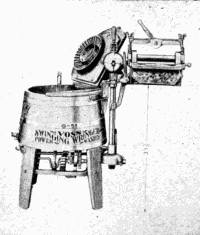
Fig. 87-a. Washing machine.
Other machines combine the
two methods of washing—forcing
water thru clothes and
rubbing them at the same time.
162. Cylinder Washers. Cylinder
washers contain a perforated
barrel-like device, into which
the clothes are placed (Fig. 88).
This cylinder has cleats on the inside
to raise the clothes as the cylinder turns and drop them
when they reach the highest point in it, back into the water,
thus pounding water thru them and rubbing them against
the side of the cylinder as they are raised. This is the type
used in most laundries. A cylinder turned by an electric
motor is made which can be placed in the stationary wash[134]
tub in small apartments. The tub then serves as the outer
part of the washing machine.
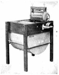
Fig. 88. Cylinder washer.
163. Rotary Washers. In the rotary, or milk-stool, type
of washer, sometimes called
"Dolly" (Fig. 89), the stool-like
contrivance which presses
against the clothes must be
turned half-way around in one
direction, and then back the
other way, to prevent twisting,
tearing or otherwise injuring
the clothes. The clothes are thus
rubbed against the corrugated
sides and bottom of the machine,
and thru the water. Never
put too many clothes in this type
of machine because too tight
packing causes the machine
to tear them.
164. Machine with
an Oscillating Washing
Device. This washer contains
an oscillating device
for rubbing the clothes
over the corrugated bottom.
The rubbing device
is also corrugated and is
put on top of the clothes
and moved backward and forward, thus rubbing them
between two wash-boards (Fig. 90).
[135]
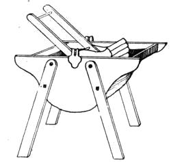
Fig. 90. Oscillating washing
machine.
165. Oscillating Washers. Oscillating washers have
corrugated bottoms. The clothes are put into the machine
with the wash water. The
washer rocks, throwing the clothes
backward and forward thru the
water, loosening and squeezing
out the dirt. This washer works
easiest when the machine is well
filled with water.
166. Locomotive Washer.
The locomotive washer (Fig. 91)
slides backward and forward, thus
churning the water and clothes. It is operated only by power.
A heating unit, usually gas, in the base of the machine
keeps the water hot.
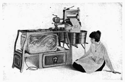
Fig. 91. Locomotive washing machine.
167. Centrifugal Washer. A centrifugal washer (Fig.[136]
91-a) contains a perforated basket which whirls in the water
contained in the machine. The clothes are placed in the basket,
rolled into bundles. The rapid whirling thru the water
removes the dirt from the clothes.
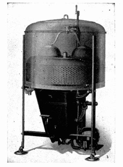
Fig. 91-a. Centrifugal washing machine.
168. Care of Washers. The bearings and other motor
parts of a washing machine should be kept oiled. Keep belts
tight. Run the machine about ten minutes each while the
clothes are in the first wash water and the two sudsy waters,
and five minutes each for the hot and the cold rinse waters.
Blueing had better be done in a tub.
Wooden machines must dry out occasionally, or else they
get slimy. Do not let them get dry enough to crack. Air
the machines after use. Cover them when not in use to keep
them clean.
[137]
When a gasoline engine is used in operating a washing machine,
it must be set so that the belt will pull straight on the
pulley wheel of the machine. The belt should be tight enough
to prevent slipping. Stationary washers are set to avoid
such troubles, but those which are moved from place to place
must be adjusted by the operator.
The pulleys must be adjusted to turn at the number of
revolutions per minute directed for the washer used. This
usually does not exceed 150 revolutions of the motor wheel
per minute.
Water motors must receive more than 25 pounds of water
pressure to operate a washing machine.
[138]
CHAPTER XXIV
Wringers
169. Roller Wringer. The kind of wringer in most general
use is the one made of two rollers rotating in opposite
directions, the clothes being drawn in between the two by
friction, and the water pressed out. (See Fig. 88.)
The rollers in modern wringers are made of a composition
of rubber. They are adjusted so that they may be brought
close together or moved apart. When wringing thin articles,
the rollers should be set close together, and when wringing
heavy articles, they should be set far apart. This adjustment
of the wringer helps to do better work and save wear
and tear on clothing and wringer.
170. Care of Wringers. The bearings should be kept
oiled, but oil must be kept off the rollers, as it rots them.
Keep the rollers washed clean. Soap and water will remove
the dirt which collects on them. If this does not clean them,
wipe the rollers in a weak solution of ammonia.
If the rollers get badly stained, wipe them with a cloth
dipped in kerosene. Wash this off immediately, as kerosene
dissolves the rubber as well as the dirt.
Never leave a wringer with the pressure on the rollers when
not in use. The pressure is either adjusted by thumb-screws
or by a clamp. Loosen these when thru with the wringer.
171. Centrifugal Wringer, or Dryer. The centrifugal
wringer, or dryer, consists of a tub, inside of which is a smaller
tub with perforated sides. There is a drain at the bottom of
the outside tub. The wringer is attached to a device for[139]
making the inside tub turn rapidly. The power used is either
hand or machine (Fig. 92).
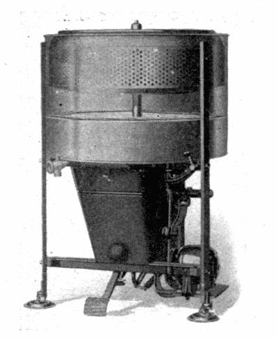
Fig. 92. Washer and dryer.
The rapid turning of the inner tub for three minutes throws
the clothing and water in them to the outside of the revolving
center. This tub being perforated, lets the water thru while
retaining the clothing. Thus, the clothes are wrung as dry as
in a wringer of the roller type. If the machine is turned a
longer time, the clothes can be wrung entirely dry.
172. Care of the Machine. When loading centrifugal
wringers, put the heavy pieces at the bottom of the basket.
Put articles in basket in bunches, and pack fairly tight. Do
not have loose ends hanging out. Fold sleeves into garments.
Load the basket full if there are clothes enough. A cover
helps to hold the clothes in place. Load so that it runs even
and does not wobble.
Never hold your hand on the extractor after it has started.
[140]
173. Combination Washer and Wringer. The centrifugal
washer and wringer combined is built so that the basket
can be lowered into a tub of water. The clothes rotating in
water are washed. After this is accomplished, the cylinder
is raised, and, when rotated, serves as a wringer of the centrifugal
type.
Load the washer with fewer clothes than for wringing.
Roll each garment into a bunch before putting it into the
washer.
Centrifugal wringers are used also as dry-cleaning machines.
For this use, they should be operated out of doors and at a
slower speed than when water is used. Friction heats gasoline,
causing it to evaporate rapidly. The friction between
clothing, tub and gasoline when turned at a high speed may
produce a spark which will ignite the gasoline.
[141]
CHAPTER XXV
Mangles and Irons
174. Construction of Mangles. Mangles are made of
rollers rotating in the same direction, one moving faster than
the other, set close together so that they press the clothes
smooth, or they consist of one roller rotating over a stationary
surface called a shoe (Fig. 93).
175. Cold Mangles. When no heater is attached to the
shoe or one roller, the mangle is a cold mangle. It smoothes
clothes, but does not do as good work
as a heated mangle. There is almost
nothing about mangles to get out of
order. The only caution necessary is
to keep the bearings oiled, have
guards so as not to catch hands in
the power machines, and loosen the
roller so that it is not pressed onto
any surface when not in use.
176. Heated Mangles. The
heated mangles have the heat applied
to one of the rollers or to the shoe. They may be used cold.
The heat may come from gasoline, gas, electricity or kerosene.
The management of the heating unit is the same as for a
stove using any of these fuels. The same care should be
taken of the burners as of stove burners.
177. Care and Use of Mangles. (1) Have the clothes
damp before putting them thru the mangle. (2) Protect the
mangle from dust at all times. (3) See that belts are properly[142]
adjusted on mangles. (4) The covering put on mangle rollers
must be of even thickness, or they will not do good work. (5)
Do not mangle starched garments, or those on which are
many or large buttons. (6) Wax the steel roller while it is
warm, and wipe it clean with a cloth (Fig. 94). (7) Always
remove pressure when not using mangles.
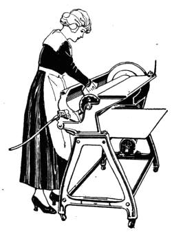
Fig. 94. Waxing roller
of mangle.
178. Flat, or Sadirons. Irons are of two kinds—those
which must be heated on a stove, and the self-heating ones.
The weight of the iron governs the
amount of heat it will absorb, and
this is the amount that it will give
up in ironing. Heat is needed to
dry clothes, and as the cloth can be
smoothed best when damp, but will
wrinkle again unless dried while
smooth, heat is essential to the ironing
process.
The weight of the iron helps in
the smoothing process. The heavy
irons do the best grade of work, but
are harder to manipulate. The
most satisfactory iron for a woman of average strength to
manage weighs six to eight pounds.
The following points should be remembered in using the
iron: (1) Rub rusty irons with bees'-wax or paraffine and
wipe with a cloth. (2) Wash irons frequently, and rub with
sand soap, Dutch cleanser, ashes or salt to polish them. (3)
Rinse in boiling water and wipe dry. Warm on the stove and
rub with bees'-wax, and set away. (4) Before using, wipe
with a cloth. (5) Do not wash electric irons—rub with wax[143]
or paraffine. Wipe off with a clean cloth. (6) It has been
found by tests that the time required in heating the self-heating
iron usually equals the time required for the iron to cool
after the heating has been stopped, but
that an iron cools faster on wet, heavy
cloth than on thin, dry cloth.
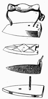
Fig. 95. Parts of
electric iron.
179. Charcoal Irons. Charcoal is
no longer used for heating irons. It makes
too much dirt. Difficulty is found, also,
in keeping charcoal irons at a constant
temperature.
180. Electric Irons. An electric iron
(Fig. 95) is made up of a heavy nickel-plated
base, a block of iron which holds
the heat, and a heating unit of small wires,
or a plate, thru which the current passes,
meeting resistance. Since resistance
against the flow of an electric current produces heat, the iron
is heated. It has a handle and shell covering the heating unit
to protect the hand and prevent loss of heat thru the top.
Getting electric irons too hot injures the heating unit, as
electricity can heat metals so hot that they melt. Excessive
heat may disconnect the circuit by burning the wires in the
iron, or it may melt the metal so as to form a short circuit.
Always follow exactly the directions for connecting and
disconnecting the iron with the current. Some say disconnect
at the plug between iron and cord, or others the plug
placed near the socket (Fig. 95-a). The weakest part in irons
is likely to be in the attachment plug. When connecting the
plug to the iron, be sure to get it back in place each time. A[144]
plug that does not fit well into place may cause sparking and
develop sufficient heat to burn off the insulation from the
cord, if not the fuses of the system to which the iron is attached.
Never attach an iron to a lighting system without making
sure that the iron is made to be operated on the voltage of the
current to which is is connected. If it is not the same, attaching
the iron may either burn out the fuses of the lighting
system, or ruin the iron.
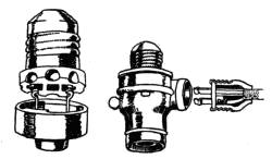
Fig. 95-a. Connecting plug for
electric attachment.
Operate the iron at a good temperature for ironing, and
take care to keep it from getting
hotter than is required.
181. Gas Irons. Gas irons
are attached to a tube leading
from a gas pipe. There is a
burner inside the iron which is
generally a straight rod with
perforations in it for the escape
of the mixture of gas and air. The air mixes with the gas at a
point near where the gas pipe enters the iron. The principle
of heating an iron is the same as the heating of a gas stove
(Fig. 96).
The burner in the iron is lighted, and as soon as it has
heated the iron, the ironing can proceed. The only difficulties
encountered in using this kind of an iron are that a
quick, jerky stroke may blow out the flame, and if the work is
being done in a drafty place, the iron may not heat evenly.
These difficulties can be overcome, however. The person
using the iron can learn to use a stroke which will be rapid and
still not put out the flame. The ironing board may be protected[145]
from drafts. A gas iron is safe and practical. It is
easily controlled by the valve admitting the gas.
182. Acetylene Irons. Acetylene irons are similar to
gas irons, the difference in them being in the construction of
the burner.
183. Alcohol Irons. Alcohol irons have a tank attached
to them which holds about a half pint of alcohol. This iron
is similar to the gasoline iron shown in Fig. 97. Some alcohol
is turned into the iron, and then the valve is closed. This alcohol
is lighted with a match and used to heat the generator
in the iron so that it will be hot enough to change the alcohol
into vapor. As soon as this is done, the alcohol is again
turned on and lighted. The burners in these irons should be
kept free from dirt. Like gas irons, they should be used with
a stroke which will not put out the fire. They cannot be operated
in a strong draft. The heat in them can be regulated
by the valve which controls the flow of alcohol.
————
184. Gasoline Irons. There are two kinds of gasoline
irons. In one the tank is a part of the iron (Fig. 97), and in
the other the tank is many feet away, where the gasoline is
changed to gas by a cold-process gasoline gas machine and
connected with the iron by a flexible tube. These latter operate
like other gas irons.
[146]
Gasoline irons with the tank attached are operated the
same as alcohol irons. The danger in these irons comes
in the tanks becoming overheated. Alcohol is used first to
heat the generator because it will not smoke the iron. The
gasoline, when lighted, should burn with a blue flame.
The tank should be one which has been tested to stand a
high gas pressure, as the gasoline in the tank may become
heated and vaporize. The gas so formed must not escape
into the room, where it might be ignited by a spark. If not
allowed to escape, it exerts considerable pressure inside the
tank. If the pressure becomes too great, it will break the
tank, escape and ignite from the flame in the iron. The opening
for filling must always be kept closed when the iron is in
use.
Questions for Part VI
1. Explain the construction of various types of washing machines.
What are the advantages of each?
2. What care should a roller wringer receive?
3. How does a centrifugal wringer dry clothes?
4. How does a mangle differ from a wringer?
5. What is the difference in care that should be given to a plain flat
iron and an electric iron?
[147]
PART VII
House-Cleaning Equipment
CHAPTER XXVI
Vacuum Cleaners and Cleaning Tools
185. Principle Upon Which Vacuum Cleaner Works.
The principle of a vacuum cleaner is that, thru suction, dust
and dirt are drawn from the floor or other surfaces into some
container. If the power of the cleaner is sufficient, it may
pick up anything—but cleaners having a moderate amount of
power are somewhat more discriminating. They do, however,
remove the fine, greasy dirt that brooms, brushes and
carpet sweepers fail to get. The coarser dirt and ravelings
may be taken up by a carpet sweeper, with a brush, or picked
up by hand. The brush is combined with the cleaner in many
machines (Fig. 98).
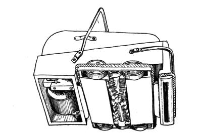
Fig. 98. Brush and vacuum cleaner combined.
[148]
186. Different Kinds of Vacuum Cleaners. There are
cleaners with bellows, pumps or fans to draw in air and dirt.
The ones with bellows in them work on the principle of a bellows
which is reversed so that when the air is drawn in, it
brings the dirt with it. The other kind works with a fan
which draws or sucks air from the floor thru a nozzle into the
machine. In the machine, the dust is filtered out of the air
and collected in a pan.
The machines with fans in them are mostly power machines,
as the fan must revolve very rapidly. The hand machines
are mostly of the pump and bellows types. Some are
combined with the carpet sweeper, making two machines in
one. With this device once going over the floor is sufficient
for removing both coarse and fine dirt. The hand machines
do not have as much power of suction as the power machines,
but they do very satisfactory work. They are more effective
than a carpet sweeper in removing dirt, but they do not get as
much of it as the stationary cleaner. Removing the sharp
grit from rugs and carpets lengthens the life of them so that
the more grit a cleaner can remove without tearing the carpet,
the more valuable it is.
When the pump type is being used, the piston is drawn up,
drawing with it air and the dirt which is present at the point
from which the air comes. A cloth filters out the dust. The
air escapes from the machine before the piston is lowered to
draw in more air and dirt. If this were not true, the dust
would be forced back as the piston was lowered.
187. Nozzle of Vacuum Cleaner. The nozzle, or point
of entry of air into the machine, is an important part of a
vacuum cleaner. This is constructed so that it fits the surface[149]
from which the dirt is to be drawn, insuring the drawing
up of dust as well as air.
The dirt is drawn from only a few square inches of surface
at one time. The thoroness and rapidity with which the dirt
is removed depends upon the strength of the suction or the
power of the machine. Thus, hand machines may have to be
moved over a surface several times if it is very dirty in order
to get all the dirt.
Plain solid nozzles work best on carpets and other surfaces
of similar kind. They are not effective on hard floors, but
this is not essential, as dirt can easily be removed from smooth
surfaces with a brush.
188. Cautions in Using Vacuum Cleaners. The difficulties
to be met with in vacuum cleaners are leaks. First of
all, the machine must be fitted together perfectly; if not, the
dust drawn into the machine escapes into the air of the room
instead of into the collection pan or chamber.
Machines are made air-tight, but to be cleaned, they must
be taken apart. In putting them together, the housekeeper
must take pains to fit them together perfectly.
Never neglect to empty the dust chamber. Keep the machine
properly oiled. A punctured bellows or a leaky dust
strainer will cause dust to escape after being drawn into the
machine. These have to be remedied with new parts. Some
machines leak because of improper manipulation, such as a
too-fast or too-jerky motion in operating them. The directions
for each machine tell how to use it—such directions
cannot be given here because they differ so much.
When the pan has become over-full of dirt, the machine will
necessarily throw out dust as well as air. Letting the machine[150]
get over-full of dust may ruin the machine by making some
part leak continuously.

Fig. 99. Electric vacuum
cleaner.
189. Difference Between Hand and Power Cleaners.
Power machines differ from hand ones in that they are run by
motor power (Figs. 99 and 99-a). They may have larger
collecting chambers and may be
stationary in the cellar and connected
to the rooms by long
pipes (Fig. 100). They must
likewise not be over-full of dust.
They must be kept properly
adjusted. As the operation of
the mechanism shakes the machine,
it may loosen screws and
nuts, so they must be kept
tightened. The motor must
also be kept in order. The motors
used for vacuum cleaners
are the same as those used on
other power devices. They may
be small electric motors, forming a part of the machine, or
large motors which operate several machines.
In any case, they must be given the same care as any other
motor of the same type. (See Chapter XXXVIII.) If they
become overheated, they will not work well. They must be
kept lubricated to avoid friction, and they must be kept
properly adjusted. Fig. 100-a shows a number of different
attachments for vacuum cleaners.
[151]
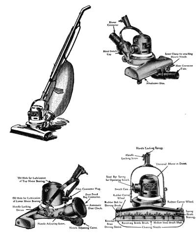
Fig. 99-a. Electric vacuum cleaner, showing parts.
[152]
190. Carpet Sweeper. A carpet sweeper is a combination
of brush and dust pan. The advantage of this device is
that the dust is gathered into the machine as the brush
rotates, due to the action of the wheels on which the machine
moves. The dust is collected into pans at each side of the
brush; these are covered so that the dust does not fly into the
air as much as otherwise would be the case (Fig. 101).
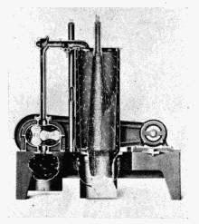
Fig. 100. Stationary vacuum
cleaner.
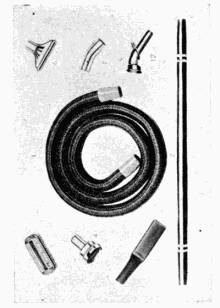
Fig. 100-a. Nozzles for
vacuum cleaner.
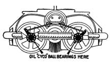
Fig. 101. Section of carpet
sweeper.
————
Oil the sweeper regularly about once a month by putting
one drop of oil on the ball
bearing on the hub of each
wheel. Failure to oil carpet
sweepers causes them to wear
out quickly, to squeak, and to run hard. More oil than is
needed only gathers dust and gums the sweeper.
Empty the sweeper (Fig. 102) each time it is used, even
during the sweeping if necessary. Don't fill it to overflowing.[153]
Always open the pans by pressing on the dump levers, not by
taking hold of the pans. Don't let the brush get tangled with
hair, ravelings, etc. Take it out occasionally and clean it
(Figs. 103 and 103-a). Cut along between the spiral rows of
bristles with a sharp knife or shears, and the ravelings and
hairs can be picked or combed out easily without injuring the
brush (Fig. 104). Never try to pull them off whole. Also
remove any accumulation of dirt or ravelings which catch in
the wheels or bearings. Don't let dirt collect in any part of
the machine. Keep it clean. Good sweepers work best without
extreme pressure on the handle. Never put oil, water or
any liquid on the bristles. Don't keep a sweeper on a warm-air
register—it takes the life out of the bristles.
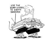
Fig. 102. Emptying
sweeper.
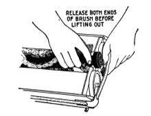
Fig. 103. Releasing brush
in
sweeper.
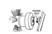
Fig. 103-a. Details of
construction of carpet
sweeper.
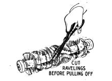
Fig. 104. Cut ravelings
from brush.
[154]
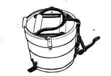
Fig. 106. Another type of
mop wringer.
————
191. Mop Wringers. There are two kinds of mop wringers
to attach to pails. One is made of two flat surfaces which,
when pressed together with the mop between (Fig. 105),
squeeze the water out of it, and the other is made of two
wringer rollers which, when brought together by a lever after
the mop is put between them, rotate as the mop is pulled upward
and wring out the water (Fig. 106).
Questions for Part VII
1. How do vacuum cleaners pick up dust?
2. Describe some type of vacuum cleaner.
3. What care should be given a vacuum cleaner?
4. Tell how to clean a carpet sweeper.
[155]
PART VIII
Devices for Preparation and Conservation
of Food
CHAPTER XXVII
Pots, Pans, and Other Devices
192. Materials from Which Utensils Are Made. Since
there is considerable choice in utensils made from different
materials, the housekeeper may like to know something about
these materials and about their care, and the effect of acids
and alkalis upon them.
Russia iron is one of the older materials for pots and pans,
and it still holds a place in cookery, for it makes bread, loaf
cake and cooky pans, which give to the food a thin, brown
crust, due, undoubtedly, to the way in which it conducts
heat. (See tables on page 158.)
Tinned metal, which is well tempered, also, gives a thin,
brown crust to layer cakes and pies. It makes good bread,
loaf cake and cooky pans. Most of the cheap tin of today is
iron-coated with very little tin. It does good work, but
utensils made of it cannot be kept as well polished and as attractive
in appearance as more heavily-tinned ones.
Sheet iron, heavy steel and cast iron make the most popular
frying pans. The heavy iron, holding heat as it does,
makes a desirable brown coating on most foods without the
danger of burning experienced with frying pans of other[156]
materials. This is due to specific heat and conductivity of
the metal. Sheet-iron frying pans are useful in cooking foods
which are wanted on short notice. The small-sized ones are
most in use.
193. Aluminum Alloy. Satisfactory frying pans are
made from aluminum alloyed with other metal and cast.
Real aluminum frying pans warp. They do not brown the
food as well as materials that conduct heat less rapidly.
194. Cast-Iron Utensils. Heavy cast iron finds special
favor in the making of pot roasts, bread sticks and popovers.
It browns the roast and makes a thick crust on bread sticks
and popovers.
All iron or tin utensils give better service as they become
tempered with use. They must be kept dry in order to prevent
rust. Do not use them for cooking acid foods.
Granite, cast aluminum and Russia iron are the popular
and satisfactory materials for roasting pans.
195. Earthenware. For casseroles and bean pots, earthenware
is a favorite material, the heavy glass gives equally
good results. These materials are fitted for long, slow baking
of food. They hold heat and conduct it to the food in such a
way as to produce results which are difficult to duplicate with
utensils of other materials.
196. Aluminum and Graniteware. Stew pans are
proving satisfactory when made of aluminum and of high-grade
graniteware. An assortment of pans and double boilers
containing utensils of each material gives the best results,
as the granite is most desirable for cooking some acid and very
salty food, while aluminum is light and satisfactory for preparing[157]
other dishes. Never let food stand in aluminum or
granite dishes after being cooked. High-grade graniteware
is not as readily affected by acids as the low, cheap grade.
Enameled ware, which is roughened by a dilute solution of
vinegar, is likely to contain substances injurious to health.
Ink will not stain good enameled ware. Graniteware, like
glass and earthenware, makes a heavy crust on the dishes
being baked in them. Graniteware is metal, coated with a
sort of glass. It must be treated like glass. It cracks when
dropped. Never set it on a hot stove when empty or cold, as
the heat of the stove will crack it as it will glass. When hot,
do not set it on a cold marble or a metal table top, as sudden
changes in temperature will crack it. With proper care,
granite and enameled ware give good service.
Graniteware is proving desirable for making utensils for
use on electric stoves, the conductivity of the glass coating
being so low, that it conducts the heat to the top of the
pan slowly so the food in it gets to cooking quicker than in
utensils made of most of the other materials.
Aluminum is easily dented and warped by extreme heat.
It is attacked by some strong acids and strong solutions of
salt, soda and fruit juices. Aluminum may be hardened by
the addition of six to seven per cent of copper so that it can be
cast into utensils. Great care must be used not to use cleaning
powders which contain strong alkalis for cleaning aluminum
ware. It has light weight, and, when polished, is very
attractive. With proper handling, it gives good service.
197. Mixing Spoons. The wooden mixing spoon gives
best results, as it does not mar the utensils, and the handle
does not become as hot as metal. Hard maple or orange[158]
wood cut in a plain design makes the best spoon. Acids do
not attack it. Plated silver or solid nickel spoons come next
in usefulness. Softer metals wear off too fast to be satisfactory.
Nickel is a most desirable material for household utensils,
but is very expensive. It is not in common use in this country.
TABLE SHOWING CONDUCTIVITY AND SPECIFIC HEAT
OF METALS
| |
| Metal |
Conductivity |
Specific Heat |
| Silver |
1 |
. |
00 |
0 |
. |
0559 |
| Copper |
|
. |
74 |
|
. |
0923 |
| Aluminum |
. |
48 |
. |
2022 |
| Tin |
. |
15 |
. |
0509 |
| Glass |
. |
0017 |
| Silicon |
|
. |
159 |
at |
10° C. |
| |
. |
2029 |
at |
232° C. |
| Nickel |
. |
1084 |
| Tungsten |
. |
035 |
| |
[159]
CHAPTER XXVIII
Parers, Seeders, Grinders, Slicers, Etc.
198. Fruit and Vegetable Parers with Knives. Parers
of the type with a knife have a fork-like device on which the
fruit or vegetable is held while a knife blade, attached to a
shaft governed by a spring, is pressed against the fruit or vegetable
so that it cuts off a thin layer of the surface. Both the
fruit and the knife are caused to rotate
so that the whole surface of the
sphere-like object will be covered by
the blade of the knife during one or
more revolutions of the wheel which
operates them (Fig. 107). The knife
is guarded so that it cuts only a thin
layer from the outer surface of the
fruit or vegetable. After the knife
has made the complete journey over
the surface, a device attached to the machine pushes the object
from the fork so that a new one may be put in its place.
Parers are quite complicated devices, but they have been perfected
so that they are not clumsy, and some can core apples,
stone peaches and slice the fruit.
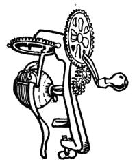
Keep this type of machine dry so that it will not rust. Do
not put it into water. Wipe off the blade of the knife and the
fork when thru paring, so that the acid of the fruit will not
discolor them and dull the knife. Keep the other parts dry
and oiled. In time the spring governing the knife becomes[160]
weak and the machine will not do good work. This spring
can be replaced on some machines. Parers are usually made
of cheap material so that a new machine costs less than
the repairs.
199. Parers Which Grate Off Skins. Another type of
parer is a grater-like device. This is used in larger establishments
than the ordinary
home, but is useful where
there is much canning
of hard fruits or vegetables
to be done at home. It
consists of a container,
the inside of which is rough like a grater. The vegetables
or apples are put into the container with water enough to
float and separate them, and the whole is agitated so that
the vegetables coming against the sides have the outer
surface removed or grated off. The water acts as the
medium for moving the vegetables and for removing the bits
of skin from the sides of the parer.
————
Keep this parer clean by scrubbing the inside with a stiff
brush and rinsing well with water after using. Keep in a dry
place.
[161]
200. Seeders and Stoners. Seeders and stoners are
constructed to punch out the seeds which are contained in
cherries, grapes, raisins, etc.
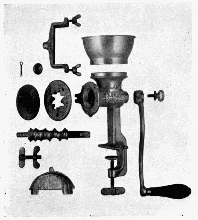
Fig. 110. Parts of Corona grinder.
201. Cherry Stoner. A simple cherry stoner (Fig. 108)
consists of a small platform with a rod slightly smaller in
diameter than a cherry stone. The cherry is put on an inclined
plane so that it rolls over the hole. The cherry usually
stays on the rod until this rod is lifted; then it passes between
two guards which pushes the cherry off on another incline,
where it rolls into a pan (Fig. 108).
[162]
There are several makes of stoners, but most of them
work on this principle, whether the rod is lifted by hand or
moved by a crank.
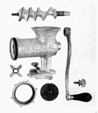
Fig. 111. Parts of Universal grinder.
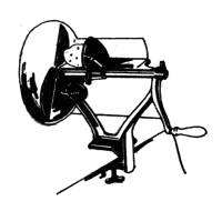
Fig. 112. Vegetable slicer.
202. Grinders. Grinders are of two principal types—the
roller and the burr. Coffee and other hand mills are of
the burr type (Figs. 109 and 110). The food passing between
these rough surfaces is ground to a fine powder as one is
turned on the other.
203. Choppers or Meat Grinders. Choppers or meat
grinders, as they are sometimes called, consist of a spiral[163]
channel, thru which the food is pushed along. Knives are
placed in the sides of some machines to chop the food as it
passes, while in others the knives are only at the outlet.
Keep the fingers out of the hopper
when the chopper is being operated.
Keep the machine clean and dry
when not in use (Fig. 111).
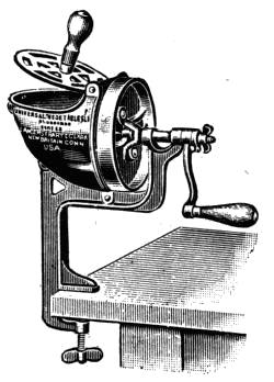
Fig. 113. Universal vegetable
slicer.
204. Choppers. Choppers have
been made which really chop the
food without crushing it, but these
machines are so clumsy and noisy,
that they have not come into common household use. They
consist of chopping knives which are raised and lowered
by levers and a crank.
205. Slicers. Slicers vary in
design. The following illustrations
(Figs. 112 and 113) show two different
types. Care must be taken
to guard the fingers when using
slicers. Wash the knives and keep
them dry when not in use. A
soiled knife gets dull faster than a
clean, dry one.
206. Lard and Fruit Presses;
Sausage Stuffers. Presses and
stuffers are of two types—the one
which depends on the weight exerted on a long lever, and the other
which depends on a screw to press the substances. The screw forces a
flat board or surface down upon the food as it is turned. More pressure[164]
for the size of the device can be secured with the screw
than is practical with a weight on the long arm of a lever
(Fig. 114). The stuffer is like a press, except that the food
is forced out one hole.
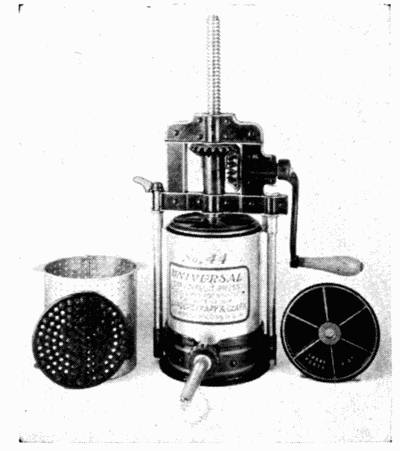
Fig. 114. Lard and fruit press.
[165]
CHAPTER XXIX
Mixers, Beaters and Churns; Coffee Pots
207. Use of Mixers, Beaters and Churns. Mixers,
beaters and churns are all devices for agitating or stirring
food.
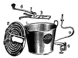
Fig. 115. Parts of bread mixer.
The simpler ones of these devices depend upon the motion
of the hand (Fig. 115), while others have their velocity increased
by means of cog
wheels.
The turning of the large
wheel turns the small wheel
as many times as number
of cogs on the small wheel
is contained in the number
on the large wheel (see Fig.
116). To get even more
speed or to apply the
power at a different angle, a series of wheels are sometimes
used. A few mixers, like the bread mixer, are simply machines
which take the hands out of the food, thus tending
to a higher degree of sanitation, and a change in the
motion which may not be so tiring as kneading. They do
not increase the speed of mixing.
Bread made in a mixer has a somewhat different texture
than bread kneaded by hand, but this does not change its nutritive
value.
208. Care of These Devices. The principal care needed
by these devices is that they be kept clean and the cog wheels[166]
dry. Very little oil should be used, as it would tend to get it
into the food. Sometimes the rivet holding a wheel needs to
be tightened, as, for example, when one becomes so loose that
the wheel slips cogs. If it is too tight, the wheel may bind
and work hard.
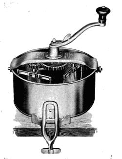
Fig. 116. View showing internal
arrangement of cake mixer.
209. Freezers. The freezer is a mixer in a can which is
in turn set in a freezing mixture
of ice and salt.
Freezing can be done without
stirring the cream. This
makes a cream filled with
crystals, while if stirred, it
will be smooth and velvety
because it freezes more evenly.
The rapidity of freezing
and the proportion of the
ice and salt affect the fineness
of the grain of the frozen
dish.
A freezer is designed not
only to stir the food, but to
scrape it from the sides of the
can. That which freezes first must be stirred into the middle
of the can; otherwise, it would form a hard frozen layer of
cream on the sides, leaving the middle unfrozen, and interfere
with the turning of the paddle or beater.
In the bottom of the outside bucket, holding the ice and
salt, is a socket into which the pivot on the bottom of the can
fits. The can turns on this pivot in the direction opposite
to which the paddle is turning. Some freezers are made so[167]
that the can stays stationary. The function of the pivot is
then to hold the can in the center of the pail so that the paddle
will be in the proper position to turn easily.
210. Care of Freezers. The pail of wood should not be
stored in a very dry place when not in use. The can and paddle
must be kept clean and dry so that they will not rust.
The bearings and wheels which turn the paddle and can must
be kept dry and oiled.
There is a hole in the upper part of the tub or pail in which
the can sets, and this should be kept open as it is placed
slightly below the level of the top of the can so as to drain off
any water from the melting ice which otherwise might get
into the can and make the food salty.
Some freezers have another hole at the bottom of the tub.
This should be kept closed while food is being frozen. It is
useful to drain off the water from the tub when the freezer is
to be repacked or emptied. It should not be opened at any
other time.
211. Churns. Churning can be done with almost any
device which agitates the cream, but the churns which are
simplest are most easily cleaned and least wasteful of butter.
They are barrels or other containers which revolve or swing
backward and forward.
Keep churns clean and well aired so they will not give up
odors and flavors to the butter. After a churn has been used,
rinse it with cold water and then wash it in hot water, to
which washing soda has been added. Lastly, rinse with
scalding water. Leave open to air when not in use, but protect
from dust and dirt.
212. Drip Coffee Pots. Drip coffee is made in a funnel[168]
or a cup-shaped device which is suspended in a coffee pot (Fig.
117). This is made either of cloth or perforated metal. The
coffee is pulverized and packed into the funnel. Cold water
is poured on top of the coffee and slowly filters thru it, extracting
flavoring substances. The water is
heated after it has filtered thru the coffee.
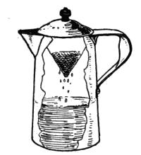
Fig. 117. Drip funnel
in percolator.
213. Percolator Coffee Pots. A coffee
percolator is a device put in a coffee
pot to hold the ground coffee above the
water and pump some of the water to the
top of the pot so that it can seep back
down thru the ground coffee (Fig. 118).
A perforated cup with a perforated cover holds the coffee.
Thru the center of this cup passes a small tube to the top of
the pot. At the bottom of the tube is a flat plate with turned-down
edges or other device which supports the pipe and rests
on the bottom of the pot. A small amount of water gets under
this and into the pipe. The heat in the stove turns the[169]
water next the bottom to steam, and this steam, in escaping,
forces the water in the pipe to the top of the pot, and raises
the device slightly so that more water flows under it and into
the pipe, and again steam is formed and more water forced to
the top of the pot. (See Sec. 161, Suction Washers.) After
being forced out of the top of the pipe, the water falls in a
spray on the cover of the cup and seeps down thru the coffee
back into the main part of the coffee pot. The pumping devices
in percolators may differ somewhat in design, but the
working principle is the same—that steam is lighter than
water and can be generated in amounts which will force water
up thru the central tube.
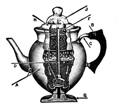
Coffee grounds must not be allowed to get into the small
tube, for they will hinder the flow of the water. The holes in
the cup and cover must be kept open. There is less waste in
using finely-ground coffee than the coarsely-ground in percolators.
A small tube brush is needed for cleaning percolators.
The coffee must not be ground so fine that it will sift thru the
perforations in the cup.
[170]
CHAPTER XXX
Dish-Washers, Canners and Dryers
The dish-washers (Fig. 119) have found a place in hotels
and large establishments, they are still in the experimental
stage for general household use.
Small machines on the market, patterned after the hotel
type, are giving good results for home use. When using these
machines, place the dishes in them in the manner directed and
use as much water as is called for.
Some dish washers work on the plan of revolving the dishes
in the water, some in forcing the water over the dishes, and
others by agitation of both dishes and water.
[171]
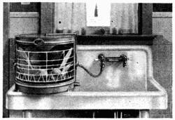
Fig. 119-a. Small dish-washer
for household use.
Keep the pan washed clean. Keep all bearings properly
oiled. Have the machine dry when not in use. There is
least breakage in the washers which hold the dishes stationary
(Figs. 119, -a, -b and -c).
One type of dish-washer has
no motor; the force of the running
water washes the dishes.
This can only be used where
the water supply is abundant
and under considerable pressure.
The washers equipped
with paddles for throwing the
water over the dishes use about a dishpanful of water for
washing the dishes, and as much more for scalding and rinsing
them. When well scalded in the
dish-washer, the dishes will dry if
the cover to the washer is left open.
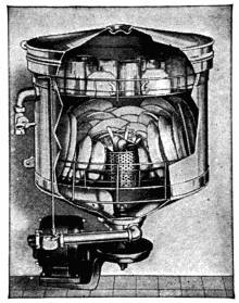
Fig. 119-b. Walker dish-washer.
214. Dish Dryer. There is
a number of dish dryers on the
market which hold the dishes separate
from each other. Into these
dryers, boiling hot water is poured,
over the dishes. There is provision
for the water being drained
away immediately, and the heat
it imparts to the dishes dries them.
(Fig. 119-c.)
215. Cleaning Silver. Silver can be cleaned in an aluminum
pan filled with water and soda. There are silver
cleaners which are merely aluminum pans with which come[172]
directions for proportioning the soda and the water. A mixture
of salt and baking soda is sometimes used, combined with
a piece of zinc in an aluminum pan. The salt, soda, zinc and
silver are put into the aluminum pan and set on the stove.
The action of the salt and soda on the metals produces an
electrolytic action which brightens the silver.
Do not use this method of cleaning on gray or colored silver.
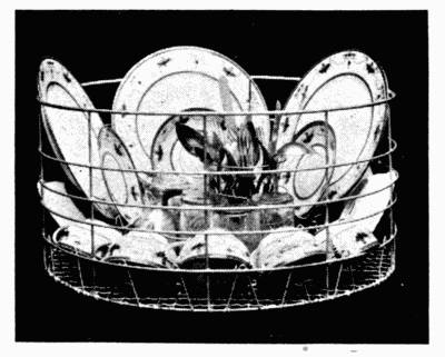
Fig. 119-c. Tray for holding dishes.
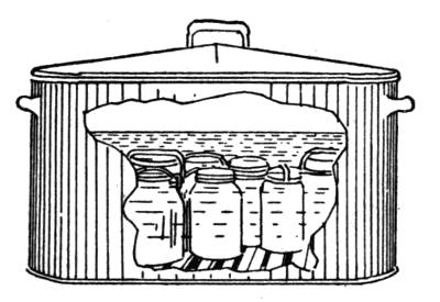
Fig. 120. Water bath canner.
216. Canners. Canners are devices for sterilizing fruit
and other food which is being canned. The wash-boiler type
consists of a boiler or kettle with a rack in the bottom to raise
the jars an inch or so from its bottom to prevent the cracking[173]
of the jars. It has a cover to keep the heat uniform. The
water in the canner must entirely cover the jar. This is
usually called a water bath, as the jars must be completely
submerged in the water (Figs. 120 and 120-a).
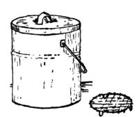
Fig. 120-a. Small
canning outfit.
217. Water Seal. Water-seal canners are like the water-bath
canners, except that the cover has a flange on it, the
depth of the boiler, and about two inches from the sides of it.
This makes a jacket of water between
the flange and sides of the canner. This
causes the temperature inside to rise
about two degrees above the ordinary
temperature of boiling water. Food can
be sterilized in a little shorter time in
this canner than in the ordinary water
bath. It is as important that the water entirely cover the
jar in this canner as in the water bath.
218. Pressure Canners. Pressure canners are made
very strong and have covers which fit
tight, making it possible to raise the
temperature in them considerably
above the boiling temperature of
water, so the food may be sterilized
in a very short time.
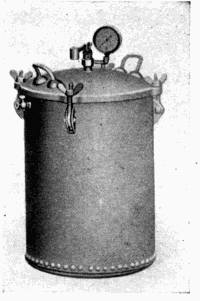
Fig. 121. Pressure canner
showing pet cock.
The pressure canner has either a
rack or a perforated pail on the inside
to raise the jars from the bottom
as in other canners. It is also fitted
with a steam gage which registers
the pounds of pressure in the canner.
Five to fifteen pounds pressure is[174]
used for canning. The amount of pressure needed and the
time of sterilizing depends on the organism present. A
higher pressure is an indication of a higher temperature in
the canner. After the jars are filled and put in the canner,
the cover is fastened down tight by thumb-screws. There is a
pet cock which is kept open when the canner is first heating,
to let the air be forced out by the first steam which forms. As
soon as the steam begins to escape, the pet cock is closed and
the temperature inside of the canner begins to rise above the
temperature of boiling water (Fig. 121).
On the canner is a safety valve which is set so that the instant
a certain number of pounds of pressure is reached, it is
lifted up by the steam. Some of the steam then escapes, thus
preventing the pressure in the canner becoming so great that
there is danger of its exploding.
219. Use of the Canner. Water is put into the canner
to reach to the bottom of the rack. The jars are filled according
to canning directions and are set in the canner. When
the jars are in, the cover is adjusted to the canner and screwed
on tight so that no steam will escape between the cover and
the canner. The pet cock is left open until steam begins to
escape thru it as the canner is heating on the stove. When
steam begins to come, the pet cock should be closed, and the
steam-gage hand then begins to turn, indicating that the
pressure in the canner is rising.
When the steam-gage reaches the point desired, the safety
valve is adjusted so that the steam will escape should the
pressure continue to rise. Until the operator knows where to
set the weight to the safety valve, leave it well out to the end
of the rod until the pressure in the canner has reached the desired[175]
point. Then move the weight to the point on the arm
of the valve which will just keep in the steam.
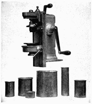
Fig. 122. Device for sealing tin can.
Be sure the cover is properly adjusted. Be sure to exhaust
the air from the canner before closing the pet cock. Keep the
fire so that the desired pressure will be maintained without
the escape of steam
from the safety valve.
When steam escapes
from the canner thru
the pet cock at a
rapid rate, it may
cause liquid to flow
out of the jars.
Be certain to let
the canner cool until
the indicator on the
steam-gage has
reached zero before
opening the canner.
When the indicator
points to zero, open
the pet cock. If a heavy stream of steam starts to escape
from it, close it again and wait a few minutes longer. Test
again by opening the pet cock; if a very little stream of steam
escapes, leave the pet cock open and wait until steam has
stopped escaping from it. Now loosen the screws holding
the cover in place. Partially loosen each screw. When this
is done, fully loosen all and lift off the cover. These precautions
are taken to prevent the operator from being burned
by steam or getting hurt by the cover being lifted by the[176]
steam. It also prevents the breaking of glass jars due to
sudden pressure changes.
Never let the canner cool so long before the pet cock is
opened that air will rush into it, due to the vacuum which is
sure to form when the steam is cooled if the pet cock is not
opened. Such a condition may break the jars.
Tin cans are sealed with a device
(Fig. 122) which folds the
edge of the cover over the top of
the can so tightly it will not leak.
220. Dryers. Dryers are devices
to hold the food being dried
in a thin layer so that the air can
be circulated thru it freely. Sometimes
they are devised to direct
currents of air thru the drying material. If the air is heated,
the drying is hastened (Fig. 123).
A sieve on which food is spread hung above the stove is a
simple drying device and one of the most practical for home
use. The heat currents rising from the stove pass thru this
and dry the food.
Many dryers are constructed on this same principle, having
a heating unit below and trays of food above. These trays
have to be shifted from time to time, as the moisture from the
lower ones rises with the heat to the upper trays, thus retarding
their drying. The top trays, if too numerous, are useless
on this account. Two or three seem to be all that can be used
with advantage at one time in home dryers, the some machines
are made with many more.
[177]
Another type of dryer has a fan device in it which forces the
air thru at a faster rate than would be accomplished by heat
alone. Such air should pass thru a strainer. Ordinary air,
even when drawn from a clean room, carries much dust with
it, and if the dust is not strained out previously, it is strained
out by the food. This injures the quality of the product.
Large commercial dryers provide such a strainer.
221. Care of Dryers. Dryers should be kept clean.
They should not be heated enough to cook the food. Set
them in a dry, airy place.
[178]
CHAPTER XXXI
Separators and Emulsifiers
222. Cream Separators. A cream separator is a device
for separating cream from milk. Separation can be done best
while the milk is still warm (Fig. 124).
Separators should be set in a bright, dry, airy place free
from dust and dirt. Near the separator should be a convenient
place for airing and sunning the tin parts which come in
contact with the milk.
The base for the separator should be solid enough so that it
will not shake while the machine is being operated. If set on
a wooden floor, see that the boards are nailed in place, and if
the floor is thin, put heavy strips to cover several boards
across it. Fasten the strips firmly to the floor and set the
separator on them. When the machine is set up, be sure
that it is set level.
223. Different Types of Separators. There are two
types of separators—one which contains discs of metal (Fig.
125), and the other which depends upon a cylinder in which
the milk rotates (Fig. 124) for the separation of the cream
from the skim milk. Fig. 126 shows a sectional view of the
DeLaval separator.
Cream is lighter than milk, and when milk and cream are
whirled rapidly, the milk, being heavier, flies to the outside of
the container, and the cream stays near the center. Two
pails whirled rapidly made the first separator ever used, but
that was clumsy and impractical.
[179]
Modern separators consist of a pan which holds the milk,
and which lets it flow in a stream into the portion of the machine
which is being whirled rapidly by the turning of the
wheel at the side. There is a place in the rotating part which
lets the cream flow from the center into one container, and
the milk flow from the outside to another.
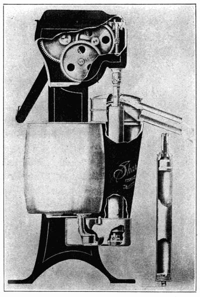
Fig. 124. Cream separator.
[180]
The parts of the machine must be fitted together properly;
otherwise, it will fail to do good work.
Always turn the wheel at the speed indicated for the machine
with discs. If there is no speed indicated, turn as fast
as needed for good separation of milk and cream. Take care
not to drop and dent any of the tin parts. Adjust for the
density desired for the cream.
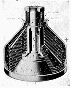
Fig. 125. Discs in DeLaval
cream separator.
224. Washing the Machine. As soon as milk has been
skimmed with the separator,
pour some water into
the bowl and run it thru
the separator the same as
the milk.
Wash the bowl and other
parts in hot water in which
washing soda has been dissolved.
Rinse in clear water,
and then scald with
boiling water. Once a
week give it a more thoro
washing, scrubbing all
parts with a brush. Sun
the parts when not in
use.
225. Oiling. The mechanical parts which whirl the
separator should be kept oiled. In oiling, follow the directions
which come with the machine. Use a good grade
of oil.
226. Whey Separator. A whey separator is a machine
very much similar to a milk and cream separator. It is[181]
used in homes where much cheese is manufactured. It
should be given the same care as other separators.
An homogenizer is a device used to give whole milk a consistency
which is much like cream.
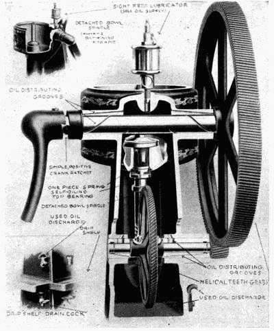
Fig. 126. Sectional view of separator.
227. Emulsifier. The emulsifier is a device for combining
dried whole milk with water, or dried skim milk with
water and butter fat so that they make a reconstructed milk
of almost the same composition as new milk. An emulsifier[182]
is of interest to the woman who lives in the city. Emulsifiers
are used in large institutions. Some have been installed in
settlement houses and public schools. They might be owned
by communities where people might use a large amount of
dried milk. In the emulsifier, the milk, water and sweet butter
are warmed. After this, they pass thru a device looking
much like a separator, but which mixes the ingredients together
instead of separating them. From the mixer the milk
passes over a cooling device, and is ready for use. This machine
should be kept clean, and the parts which come in contact
with the milk scalded out with hot water after being
rinsed with cold water.
Questions for Part VIII
1. What metals would you select for a pan to use when a thin crust
is wanted? What materials produce thick crusts?
2. For what purposes would you choose aluminum? Granite? Cast
iron? Glass? Earthenware? On what basis would you make a choice
of utensils? Why wouldn't glass make a good ice-cream freezer?
3. What are the essentials of good parers, slicers and corers?
4. What kind of dish washers are proving the most helpful?
5. Describe a silver-cleaning device. Does the use of such devices
harm the silverware?
6. What is a water-bath canner? How would you make one?
7. What may cause glass jars in pressure cookers to break?
8. How may the breakage be prevented?
9. Explain the ways in which cream may be separated from milk.
10. How do separators help?
[183]
PART IX
Sundry Devices
CHAPTER XXXII
Dumbwaiters and Other House Furnishings
228. Dumbwaiters and Window Adjustments. Dumbwaiters
and elevators are used in homes where the kitchen is
on a different floor from the dining-room.
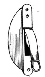
Fig. 127. Spring pulley
for windows.
The simplest ones are a set of shelves counterbalanced by
weights. When the elevator is raised, the
weights drop down, and when it is lowered,
the weights rise.
Window weights hung over a pulley in the
top of the window sash work on the same
principle as dumbwaiters—the weights help
in raising the window. The only care needed
is to replace the rope when worn.
Another window pulley is made of metal
like that in a clock spring (Fig. 127). The spring is drawn out
when the window is lowered, and the weight of the window
is just enough to hold it, so very little force is needed to raise
the window, as the spring is pulling on it, too.
229. Check Valves. Check valves are made to prevent
doors from slamming. They are used in offices and public
buildings, and, occasionally, in homes (Fig. 128). One kind
contains glycerine and castor oil, which move from one compartment[184]
to another as the door is opened and slowly flow
back as a spring pulls the door shut.
The other kind is operated by compressed air and a spring.
The air causes the steady action of the door stop.
Another type of pneumatic hinge is attached to a door
which is hung so that it would
naturally swing shut. When
the door is opened, the air is
exhausted from part of the
hinge. After it has been
opened, the slow equalization
of the air inside the door stop
and outside allows the door to
close slowly without slamming.
230. Door Fastener. A door fastener (Fig. 129) is a
small device which has a
strong spring on the inside. When the spring
is released, it pushes down on a rod which is
capped with rubber. When down, this comes
in contact with the floor and holds the door in
place. To change the position of the door, a
small lever is used to lift the rod and compress
the spring, thus releasing the door stop from
contact with the floor.
231. Window Shades. Window shades
are equipped with a spring in one end of the
roller to aid in raising it. At the end of the spring is a flat
bar which is held in position by the bracket on which the[185]
shade is hung. Small catches hold the curtain when it is at
the desired position (Fig. 130). If the spring becomes weak,
draw the curtain down. This compresses the spring. Stop
so that the clamps always fall into place to hold it. Then
remove the curtain from the brackets and roll it up by hand.
Place it back on the brackets. It can then be raised or
lowered as wanted, and will work with more power. Take
care when doing this not to wind the spring so tight that
it will draw the curtain clear around the
roller, thus letting the spring unwind or
breaking the spring.
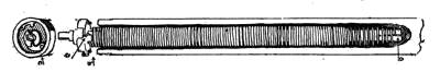
Fig. 130. Spring in curtain roller.
232. Hinges. There are some hinges
which should be of interest to women.
These are the ones for doors which swing
only one way, and for those which swing
both out and in (Fig. 131).
233. Sliding Doors. When sliding doors slip off the
slide, they may be replaced. They are hung like a barn door.
There is a metal track above the door between the walls.
The door is hung on this track by pulleys which slide along the
track. Sometimes, by accident, these pulleys are slipped
from the track. The door then must be lifted so that the pulley
can be set back on the track. Usually the door needs to be
lifted but a fraction of an inch and then pushed a little to one
side or the other to get the pulley into place.
[186]
CHAPTER XXIII
Sewing Machines
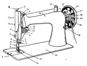
Fig. 132. Lock-stitch machine.
1. Bed Slide
2. Presser Foot
3. Presser Foot Thumb Screw
4. Needle Clamp
5. Needle Clamp Thumb Screw
6. Needle Bar Thread Guide
7. Needle Bar Bushing
8. Thread Cutter
9. Face Plate Thumb Screw
10. Slack Thread Regulator
11. Tension Spring
12. Tension Regulating Thumb Nut
13. Tension Discs
14. Thread Take-up Spring
15. Thread Guide
16. Presser Bar Lifter
17. Face Plate
18. Pressure Regulating Thumb Screw
19. Presser Bar
20. Thread Take-up Lever
21. Thread Guide
22. Arm
23. Spool Pin
24. Bobbin Winder Stop Latch
25. Belt Cover
26. Bobbin Winder Thread Guide
27. Balance Wheel
28. Bobbin Winder Pulley
29. Bobbin Winder Spindle
30. Bobbin Winder Worm Wheel
31. Stitch Regulating Thumb Screw
32. Bed
33. Throat Plate
34. Feed Plate
234. Different Types of Sewing Machines. There are
two types of sewing machines in use—the chain-stitch and the
lock-stitch. Sewing
machines are made
to run by hand, foot
or mechanical motor
power. This makes
no difference in design
or care of the
stitching part of the
machine. Motor and
foot power run the
machine faster than
hand power.
The treadle of the
foot-power machines
swings on pivots.
These should be kept
oiled and clean from
lint and thread. The
large and the small
wheels for the belt
should be oiled at
the axle.
235. Lock-Stitch Sewing Machine. A lock-stitch
sewing machine (Figs. 132 and 133) consists of shafts and[187]
wheels which move the needle, feed plate and bobbin. The
top thread is guided from spool to needle thru a tension so
that only the needed amount passes forward each time the
needle is raised after the
thread has caught in the cloth.
When there is a difference
in the size of the thread used
on the machine, the tension
must be adjusted to fit the
thread, unless the tension is
automatic. If the tension is
not properly adjusted or the machine threaded properly, the
thread will either break, tangle at the needle point, or draw
the top thread tighter than the bottom one (Fig. 134).
A longer stitch is needed for coarse thread than for fine
thread.
236. Feed Plate. A device below the needle called the
feed plate (No. 34, Fig. 132) shoves the cloth faster or slower
under the needle, according to its adjustment, thus making
a longer or shorter stitch. This
device is a rough plate which moves
backward each time the needle is
raised, and forward again when the
needle comes down. While moving
backward, the rough surface moves
the cloth, but it drops slightly below
the level of the table as it moves back into place, so does
not affect the cloth. For short stitches, it moves with a
short stroke, and for long stitches, with a long stroke. If the
feed plate becomes gummed with lint and oil, the machine[188]
will not make even stitches and may fail to move the cloth.
Sometimes it will fail to stitch. Improper threading may break
the needle thread. Too tight a tension may break it. Too
coarse thread for the size of the needle
may break the needle. A bent, blunt
pointed or incorrectly set needle may
break.
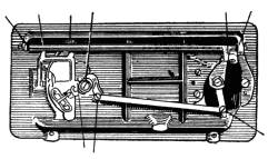
Fig. 133. Under part of machine
using a vibrating shuttle.
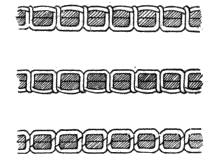
Fig. 134. Diagrams showing
proper tension.
237. Bobbins. There are two styles
of bobbins used on lock-stitch sewing
machines—the shuttle bobbin (Fig. 135)
and the round bobbin (Fig. 136), depending on the particular
type of machine used.
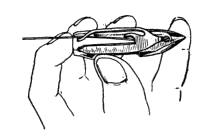
Fig. 135. Shuttle bobbin.
238. Shuttle Bobbins. In shuttle bobbins, there is a
long iron spool on which the thread is wound. This is put into
the bobbin with the twist in
the direction indicated in the
book of directions for the
machine being used, and the thread is drawn thru the slits
and holes in the bobbin which govern the tension of the
lower thread (see Fig. 135).
Put the shuttle into place and draw the thread up over the
feed plate (Fig. 137). The machine moves the shuttle backward[189]
and forward, and as this happens, the needle is timed to
drop down, leaving a loop of thread in such a position that the
bobbin passes thru it. In rising, the needle pulls the loop up
tight, and as it has passed thru the cloth, this cloth comes in
between the thread from the bobbin on the under side and the
thread from the spool on the upper side, which have been interlocked
by the bobbin having passed thru the loop of thread
from the spool as the needle carried it down below the cloth.
This is called the lock-stitch (Fig. 134). The spool bobbins
also pass thru the loop left after the needle has passed downward.
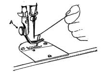
Fig. 137. Pulling up bobbin
thread.
————
239. Chain-Stitch Machine. In the chain-stitch machine
(Fig. 138), the shaft turns a device which draws a loop of
thread thru each foregoing loop, thus making a stitch similar
to crocheting, but having the cloth interlocked with the stitch.
The needle carries the thread and makes it tight or loose as
needed. The feed plate carries the cloth under the needle.
There is a tension to govern the thread. As a single thread
is used in making this stitch, no bobbin is used. The tension
must be tight enough to draw the loop of thread about the
cloth, or else the thread will tangle.
240. Cautions for All Machines. Machines should be
kept well oiled, and they must be kept free from thread and
lint, for these are the things which give trouble in machines.
Never try to draw the cloth under the needle any faster than
it is pushed along by the feed plate under the presser foot.
Pulling on the cloth bends the needle from the exact path
which it should follow.
Move the treadle with a smooth, even motion—a jerky motion
wears out operator and machine. Use only the best sewing-machine[190]
oil. Poor oil gums the parts of the machine.
Clean the machine every day it is in use. Take care to set
the needle in its proper position, and fasten it firmly in place.
241. General Instructions. Thread the machine exactly
according to instructions. If not properly threaded, it
will fail to stitch—the thread will tangle. If the bobbin is
not properly threaded, it will not have the proper tension, and
the machine cannot sew as it should. The bobbin thread will
break if it is not properly threaded thru the bobbin case. It
will also break if the bobbin tension is too tight (No. 14, Fig.
138).
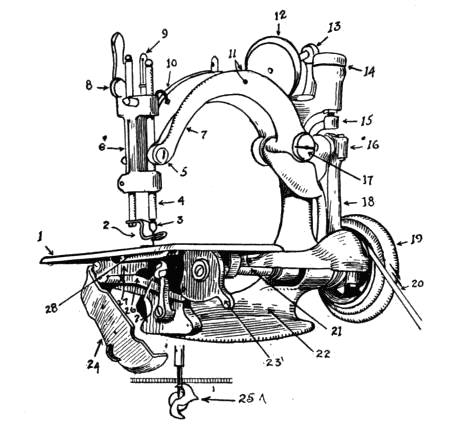
Fig. 138. Chain-stitch machine.
| 1. |
Cloth Plate |
10. |
Embroidery Spring |
19. |
Small Wheel |
| 2. |
Presser Foot |
11. |
Pull Off |
20. |
Belt |
| 3. |
Needle-Bar Nut |
12. |
Spool-Pin |
21. |
Shaft |
| 4. |
Needle-Bar |
13. |
Spool-Pin Holder |
22. |
Frame |
| 5. |
Needle-Bar Screw |
14. |
Automatic Tension |
23. |
Stitch Regulator |
| 6. |
Foot Bar |
15. |
Tension Rod |
24. |
Cap |
| 7. |
Lever |
16. |
Ball Stud |
25. |
Looper |
| 8. |
Liftee |
17. |
Lever Stud |
26. |
Link |
| 9. |
Take Up |
18. |
Connecting Rod |
27. |
Feed Bar |
| 28. Feed Surface |
[191]
Always regulate the stitch and the size of needle for each
size and kind of thread used. A table for this usually comes
with each machine, or is often stamped on the machine. Select
the thread suitable to the material. The number of a
needle is marked on the shank. Needles made for one kind
of machine will not always work on another.
An automatic tension should not be changed or meddled
with. Some tensions must be adjusted to the thread. Follow
directions coming with the machine for adjusting tensions.
Remove any thread which has become entangled in the mechanism
of the machine.
Never use a bent needle. A bent needle drops stitches on a
chain-stitch machine. Soaping the needle helps it to go thru
goods difficult to penetrate.
When a machine runs hard, it needs oil or has become gummed
up with poor oil. When gummed, clean with kerosene
oil. Thread or ravelings wound about the axles of the wheels
also makes the machine run hard. Learn to use the attachments
of your machine—take care that they do not become
bent.
The lock-stitch does not rip easily.
The ends of the thread of chain stitches should be carefully
fastened. If started from the end where the seam was completed,
the loop stitch may be easily unraveled and thus save
time when mistakes are made in sewing or when garments are
being made over.
[192]
CHAPTER XXXIV
Automobiles
No lengthy treatise on automobiles can be given here, but a
few facts of general information are well in order.
Each car has its special features, but the basic principles of
operation and control are the same for all makes. Let us consider,
first, the control of the machine on the road.
242. Starting the Motor. Open the throttle from one-fourth
to one-third way, to permit entry of plenty of gas into
the motor. Set the time control about as far down as the
throttle. Turn on the ignition switch and turn the motor
with the starter.
A cold motor may demand use of the choker before starting,
but, again, too free use of the choker floods the carburetor
with a rich, non-explosive mixture which can be removed only
by use of the starter. Should the motor flood too easily, or
should it take too much choking, have the carburetor readjusted.
Common mistakes in starting the motor are (1) too
free use of the starter, which is injurious to the battery; (2)
starting with the timer set too far down, causing back-fire.
Occasionally, a novice attempts to start a car with the gears
set and the brakes on. With the motor started and running
smoothly, shift the gears into low and take off the brake. Let
the clutch back gently to prevent the car from starting with a
jerk. In shifting gears, the throttle should be kept down to
prevent the motor from racing upon releasing the clutch. (3)
A common mistake is the attempt to shift gears with the[193]
clutch not entirely released. (4) Still another error is the failure
to release the brake on starting, resulting in everything
from a stalled motor to a stripped gear.
A difficult place to start a car is when stalled on a hill. This
is done by holding the machine with the foot brake, throttling
the motor with the hand lever, and slowly releasing brake and
engaging clutch simultaneously.
243. Driving the Automobile. In driving, many things
should be observed. The oil pressure gauge or indicator
should be noted from time to time to see that the motor bearings
are getting proper lubrication. The speed of the motor
should be such that the battery is being charged rather than
discharged, as is likewise shown by an indicator on the dash.
This is especially important when using lights at night. Keep
timer lever in correct place to prevent overheating.
The general rule for driving is—keep to the right side of the
road, the only possible exception being when passing a vehicle
going in the same direction; then go around on the left.
Stop before crossing railroad tracks, and drive slowly when
approaching cross roads. In turning corners to the left, make
the turn beyond the center of the cross road. Do not use
brakes against the motor—release the clutch. Do not use
the brake too forcibly; it will cause injury to rear tires and
skidding. On slippery roads, make it a rule to use chains
and drive slowly.
244. Care of Car. Under this heading, a few general
rules may be given. Do not persist in running a machine
when out of order. Never drive when the lubrication system
is working imperfectly. Lack of cylinder oil will ruin a motor
in a short time. Make it a rule to look at oil gauge before[194]
starting. Care of the battery consists largely in keeping it
charged and filled to the proper level with distilled water.
Tires should be kept inflated at all times. In case of trouble,
never run on a flat tire, as it will soon be worthless under such
treatment. Never drive a machine while out of order—stop
and have repairs or adjustments made.
[195]
CHAPTER XXXV
Lawn Mowers; Incubators
245. Operation and Care of Lawn Mowers. The wheels
of the lawn mower permit it both to move easily over the
ground and turn the knives which cut the grass (Fig. 139).
This means that they must be kept well oiled to work
easily—that the shaft of the wheel must not become wrapped
with grass, weeds, string or wire. Most machines are made
adjustable, and the knives are set to allow them to pass close
enough to the plate at the bottom of the mower to clip the
grass as if the machine were a pair of scissors. Keep the
knives properly adjusted in relation to this plate. Do not let
them come so close that they touch the plate but very lightly,
nor be so uneven that one end cuts grass, while the other
misses the plate so far that it will not cut.
If the knives are kept properly adjusted and the mower is
not abused by trying to cut wires, stones, or by being stored
where it becomes rusty, it will seldom need sharpening.
Keep all bolts tight.
[196]
246. Storing Mowers. When storing for the winter,
grease the knives with a heavy coat of unsalted lard, or cover
them with some other protective material.
247. Scissors and Shears. In popular language, there
is no distinction made between scissors and shears. Technically
defined, scissors are less than six inches in length. Any
similar cutting device of greater length is called shears. Both
are devices used for cutting cloth, paper, pruning trees, and
many other purposes. They consist of two knives riveted together
at some point between the handle and the point of the
blade. The two blades are so adjusted that as the open scissors
are closed, they touch lightly as they pass each other until
the tip is reached. When the scissors are closed, the blades
should touch only at rivet and tip. Scissors not so adjusted
will not cut well, even the the blades are very sharp. Dropping
scissors often bends the blades. Blades may be straightened
as well as sharpened, and thus make good metal scissors
like new.
248. Principles Upon Which Incubator Works. A
device for hatching chickens is called an incubator. In order
to hatch chickens, the incubator must keep an average temperature
of 102-1/2 degrees Fahrenheit. The thermometer
should be placed in the center of the tray and on a level with
the top of the eggs. The temperature of 102-1/2 degrees Fahrenheit
must not vary greatly during the incubation of eggs.
The incubator must also permit of suitable ventilation and
control of the moisture in the eggs.
There are incubators heated with hot water and others with
hot air. The air or water in those commonly used in homes
is heated with a kerosene lamp.
[197]
The device consists of a heating unit, a regulator or thermostat
which, acting upon a valve or damper, regulates the admission
of heat into the insulated box containing the trays of
eggs, ventilators and a thermometer (Fig. 140).
249. The Body of the Incubator. The box-like body
of a good incubator is set on strong legs which raise it to a
convenient height. The trays slide into the box on cleats
about two or three inches from the bottom of the body. They
fit so that a slit about two inches wide is left between for the
chickens to drop down under the tray as they hatch. Usually
this is near the door. If the door is furnished with a glass to
admit light, the chickens are attracted toward light and fall
thru the slit.
The walls of the incubator are usually double so that air can
be let in without making a draft. Dampers in the side of the[198]
machine regulate the admission of air. Ventilation both regulates
the amount of air circulating in the incubator and the
amount of moisture. Air from a damp room keeps the eggs
moist. Air from a dry room dries them.
250. Incubators Heated by a Lamp. Choose a lamp
which holds enough oil to last for twenty-four hours. Good
lamps are usually made of metal and as plain
as possible (Fig. 141).
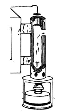
Fig. 141. Incubator
lamp.
The burner furnished with them is an ordinary
lamp burner carrying a straight, flat
wick. Metal chimneys are used, there being
enough mica in one side to permit the flame to
be seen. The chimney extends into a metal
chamber containing the hot-water pipes, or
into a chamber thru which air is taken and
heated by the chimney. The fumes from the
burning oil pass out into the room and not into the incubator.
The heated air passes thru ducts into the incubator.
These are often constructed of wood.
251. The Wick. The wick most generally found practical
is the cotton wick, such as is used in ordinary lamps. It
should be kept clean and renewed often. The lamp should be
kept filled regularly. The wick must always be kept trimmed
even, to prevent smoking.
Incubators heated by electricity have the heating unit
placed either above or below the trays of eggs. The current
is controlled by a thermostat.
252. Thermostat. The thermostat also raises the damper
over the top of the lamp and air heater (Fig. 142), when
the incubator reaches the temperature for which it is set, and[199]
lowers it when the temperature falls. When the damper is
lifted, the heated air passes out into the room and not into the
incubator. As soon as the incubator cools below this temperature,
the thermostat contracts, letting the damper drop
in place to retain the heat and direct it into the incubator.
The thermostat works the same when a gas flame is used instead
of a lamp. In electrical machines,
the thermostat operates the
switch, admitting much, little or no
current, as is needed to maintain
102½ degrees Fahrenheit.
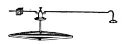
Fig. 142. Thermostat
for incubator.
253. The Thermometer. A thermometer is placed in
the incubator to guide the operator in regulating the temperature.
It guides him in adjusting the thermostat and the
heating device; that is, it shows him when to turn the wick of
the lamp up or down.
Lamps should never be turned high enough to smoke.
Smoke and gas in the room are likely to get into the incubator
and harm the growing chicks.
254. Operation of Incubator. Set the incubator level;
it is constructed to work on the level. Heated air rises—if the
incubator is not level, the highest point will get most of the
heat. It should be set in a dry room or dry cellar, which is
well ventilated and well lighted. There should be no artificial
heat in the room which is not regular. An uneven temperature
gives difficulty in managing the heating of the incubator.
The room should be free from dust.
Adjust the incubator and run it for two or three days to see
that it is operating at a constant temperature before putting
in the eggs.
[200]
Use only the best grade of oil, and use the same kind of oil
all thru one hatch. Change in oil may necessitate a
change in regulators which is not safe while the eggs are in the
incubators.
Start the incubator with a good, clear, high flame in the
lamp, so that it can be turned lower as the germs in the eggs
begin to grow and generate heat.
Start the incubator at 100 degrees Fahrenheit, and by the
second day, it will reach the temperature of 102 degrees.
Violent fluctuations of temperature in the
incubator are dangerous and should be avoided.
Accuracy in reading temperatures and in
adjusting the thermostat and ventilators is
essential. Fill the lamp and turn the eggs
regularly. Cleanliness is important. Disinfect
the incubator between hatches, and air it well.
Cresol soap and water make a good disinfectant
for incubators. Turn and handle eggs
with clean hands.
To know whether the incubator has the proper amount of
moisture supplied, weigh the trays before filling, weigh after
filling. At the end of the fifth day, weigh tray and eggs
again, subtract the tray weight, which is constant, from the
weight of the whole, and note the difference between this
weight and the original weight of the eggs. If 100 eggs have
lost 8.38 ounces, or 4.17 per cent of their weight, the moisture
is correct.
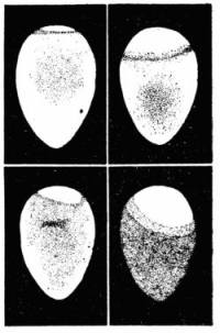
Fig. 144. Appearance of
eggs when put in egg
tester.
If they have lost too much weight, give more moisture or
less ventilation, but, remember, that pure air is essential to
incubators, so do not shut off ventilation entirely.
[201]
If not enough weight is lost, open the ventilators, and, if
necessary, for the next hatch, place the incubator in a drier
place.
255. Egg Tester. An egg tester is a device for looking
thru eggs to ascertain whether or
not they are good. It consists of
some device to keep all bright light
away from the eyes except a few
bright rays shining thru the egg.
The hole should be about an inch
long and three-fourths of an inch
wide. A metal chimney with one
such opening in the side used in a
darkened room serves as an egg
tester. A large piece of cardboard
tacked over a sunny basement
window is sometimes used, the hole
being cut in the cardboard (Fig. 143).
Hold the egg between the finger
and thumb before the opening. Look at the egg as the
light shines thru it. Fig. 144 shows how good and bad eggs
look when viewed in egg tester.
[202]
CHAPTER XXXVI
Typewriters
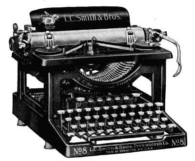
Fig. 145. Typewriter, L. C. Smith.
256. Construction of Typewriter. The typewriter is a
machine for printing letters (Fig. 145). The letters making
the imprint are attached to shafts which can each swing to one
point. Care should be taken to strike one key at a time, as
they are all made to reach the same point, and contact with
each other may cause bent shafts. If a shaft becomes bent,
the letter attached to it will not swing to the desired point, so
will be out of alignment, or will fail to leave a mark, since the
imprint is made on a roller and the letter hits only the nearest
part of the surface. The shaft may have one, two or three
letters on it. This is made possible by the use of the shift key[203]
which raises or lowers the framework to which the roller is attached,
so that when the machine is in normal position, one
set of type on the keys will be imprinted, and, upon the holding
down of a shift key and simultaneously striking a letter,
another set of type will make the imprint. On some typewriters
there are two shift keys, allowing three sets of characters
to be used. The motion of the keys turns a small wheel
which shoves the roller from right to left, and, also, turns the
spools of ribbons so that a new bit of ribbon comes under the
letter each time a key is struck. If the ribbon did not move,
the letters would soon cut a hole thru it. This ribbon carries
the ink which reproduces the imprint of the letter. When the
end of a ribbon is reached, most machines reverse its direction
so that it again winds onto the spool from which it has just
unwound. On other machines, it is necessary to release the
bar which controls the spools to reverse the winding of the
ribbon.
257. Special Features of Typewriter. Learn how to
use the attachments on the typewriter to get the greatest
service from it. If a machine is equipped with tabulating
keys, much time is saved by using them for the indentations
instead of working the space bar until the desired place is
reached, or by using both hands to release the carriage and
move it to its desired place. Some machines are equipped
with a key marked "ribbon" key. This key, when pressed,
lowers the ribbon so that no impression from it is made on the
paper. When the ribbon is removed, stencils may be cut
with the letters for mimeographic work. These are only
two examples. There are many automatic aids on each
make of machine.
[204]
258. Interchangeable-Type Typewriters. On these
machines, the type is not placed at the end of a shaft, but the
complete set of letters is put on a semi-circular plate which is
attached to a wheel which brings the desired letter to the
point wanted when the key is pressed (Fig. 146).
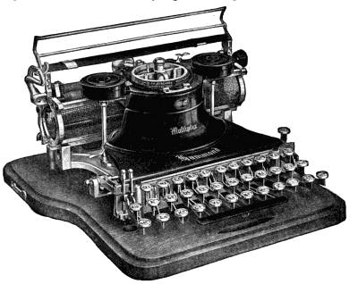
Fig. 146. Hammond interchangeable typewriter.
The change of type can be made very easily so that with
the proper semi-circular plate any one of several languages
may be written on this kind of typewriter regardless of the
characters used to represent the letters.
Charts of the keyboard are furnished with each set of letters
to guide the operator in writing. This machine requires
the same general care as other typewriters.
[205]
259. Care of Typewriters.
1) Read the directions for cleaning and oiling the machine.
Keep them for future reference.
2) Do not attempt to take the machine apart. Only readjust
parts for which such directions are given.
3) Use only the best grade of typewriter oil, and oil only
where indicated. The average machine does not require oiling
oftener than from ten to fourteen days.
4) Brush the entire machine each day before using. This
prevents the accumulation of oil and dust, which retards the
free action of the machine, and rusts or clogs the bearings and
other parts.
5) Use a stiff brush to clean the type. If the type has become
gummed with ink from lack of care, moisten the brush
with alcohol or gasoline, and brush it until clean. Avoid
cleaning the type with a sharp instrument, if possible, as it
mars the edges. However, in case of the letters having an
enclosed parts, such as c, d, e, b, g, p, a, s, c, q, it may require
the careful removal of the deposit with a pin. After this
treatment, the type should be well brushed. Keep machine
covered when not in use. With proper care, a machine
should stay in good order indefinitely. If, in any way, any
part of a machine is out of adjustment, have an expert readjust
it.
260. The Hectograph. The hectograph is one of the
simplest devices for obtaining duplicate copies of written
work (Fig. 147). It is a sheet like heavy paper or pad of
jelly-like substance on which a reversed copy of the writing
can be made and from which copies can be taken. The original
copy is written with hectograph ink on smooth paper by hand,[206]
or on a typewriter, and allowed to dry. This copy is placed
face downward on the hectograph pad, which has been moistened
and rubbed to insure the contact at all places. It is allowed
to remain here for three or four minutes. More time is
required in cold weather, as the absorption of ink by the pad
is slower. The paper is then removed, leaving a reversed impression
on the hectograph plate. Copies are then made by
placing dry paper on the impression and removing them instantly.
Twenty copies may be taken. The plate should be
washed in lukewarm water immediately after use. The hectograph
plate should be about the temperature of an ordinary
room; chilled plates produce faint prints. Never use cold
water on the plate. Keep pen
flowing freely when writing the
original copy, by wiping it frequently.
Keep the hectograph
covered when not in use.
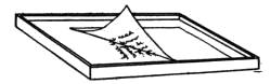
261. Mimeograph and Multigraph. The mimeograph
(Fig. 148) is a more complicated device for reproducing duplicates
than the hectograph, but more copies may be made at
faster speed on this machine and the stencils may be saved
for making more copies later. A stencil (tissue paper, usually
blue, fastened to a sheet of equal size waxed cardboard) is cut
by a typewriter. This is done by removing the ribbon and
allowing only the outline of the type to cut thru the tissue
which has been saturated with "Dermax," a liquid wax which
is brushed over the surface of the waxed paper, and the tissue
paper carefully smoothed out upon it. Some stencil paper or
waxed sheets do not require this treatment of "Dermax"; instead
a tissue or silk sheet is placed under the stencil paper.[207]
When the desired wording is cut, the cardboard is torn
off at the perforated line, leaving the four holes which attach
the stencil to the roller of the mimeograph machine. First
see that the pad on the machine is well inked, and then fasten
the stencil to the pins at the top of the roller and with bar at
the bottom, seeing that it is smooth.
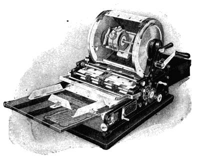
Set the adjustment which indicates the number of copies
turned out, so that it is not necessary to count them while
printing. (Full directions are printed on this adjustment.)
Place the paper on the feed board, far enough down for the
sheets to come in contact with the rollers which feed them in,
and turn the handle. If the proportion of space at top is
greater or less than desired, set the attachment for regulating
the space. Full directions are printed on each attachment of
most machines. See that the ink tank which is located inside[208]
the cylinder is kept full of the best ink. Ink the pad by pushing
the brush across the inside of the perforated cylinder.
Multigraphs differ from mimeographs in that they print the
copy from type instead of thru a stencil. The type is set in a
cylinder that is covered by an inked ribbon. Manuscripts
printed by a multigraph look more like typewriting than those
printed by a mimeograph. When turning out less than a
thousand copies, the mimeograph will be found more economical
on account of the small amount of time required in preparing
the stencil.
Questions for Part IX
1. By what means are dumbwaiters operated?
2. Can you see any relation between the construction of door stops
and force pumps?
3. What is the power for rolling up a window shade?
4. What does lock-stitch look like? How does chain-stitch differ
from lock-stitch?
5. In what way do lock-stitch machines differ from chain-stitch
machines?
6. What are the advantages of each? What are the disadvantages?
7. What is the tension? How is it adjusted? How is the length of
stitch adjusted?
9. In what ways is an automobile engine like the gasoline engine and
the electric motor used in rural homes for operating household machinery?
10. What is the shape of the knives on a lawn mower that makes it
cut the same as a pair of scissors?
11. What may be the reasons for scissors not cutting as they should?
12. What are the essential features of a good incubator?
13. What is a thermostat? How does it work? Are thermostats of
any use to the housewife on any other device than the incubator?
14. What mechanical factors are embodied in a typewriter? Find
the pulley, the levers, the springs, etc.
15. What are the differences in a hectograph, a mimeograph and
multigraph?
[209]
PART X
Motors, Fuels, and Gas Plants
CHAPTER XXXVII
Treadles and Water Motors
262. Definition of Motor. A motor is a device for
utilizing the power stored in gasoline, electricity or elevated
water for doing work. The structure of the motor depends
upon the source of its power, as does its name. Besides the
motor, there is a treadle, or foot-power motor, used in the
home.
263. The Treadle. The treadle is a small platform,
which rocks on two pivots. As the treadle is rocked, it moves
a rod attached to its outer edge, upward and downward. This
rod is then attached to a wheel a short distance from the hub,
so that the upward and downward motion of the shaft turns
the wheel. When a belt is attached to the wheel, it will run
a sewing machine or other small device.
264. Water Motors. Water motors are commonly used
in the household on washing machines and pumps (Figs. 149[210]
and 149-a.) At least twenty-five pounds of water pressure is
required to run an average-size washer. More pressure is advantageous.
The motor may be, and often is, attached to
tanks in which water is held under pressure, and used to
pump water from a cistern or well.
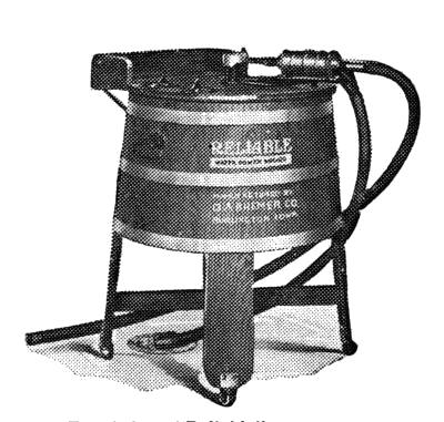
Fig. 149-a. "Reliable" water motor.
265. Selecting a Water Motor. Before purchasing any
device to be operated by a water motor, ascertain how much
water pressure you have available. Under enough pressure,
the water from a faucet will give power enough to a small-sized
water motor to run a washing machine, sewing machine
or small feed grinders. These motors are usually less than
one-half horse power.
[211]
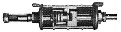
Fig. 150. Sectional view of water motor.
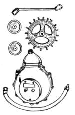
Fig. 150-a. Water motor
assembled and in parts.
266. Two Types of Water Motors. One type of water
motor is made up of a piston and valves in a cylinder (Fig.
150). The water pushes the piston to a certain point when a
valve opens and lets out the water.
The piston then moves backward
until it automatically opens another
valve, letting in more water, which,
in turn, pushes the piston forward
and again to the point where the
first valve opens. The motion of
the piston must be strong enough
to do the work. About twenty-five
pounds of water pressure is required
in moving the piston forward when
attached to a machine which might
be operated by hand by a woman.
Another type of water motor consists of cups or fans on the
rim of a wheel. As the water flows over the wheel, it pushes
it around, thus giving it power to do work provided there is
enough pressure behind the water (Fig. 150-a).
[212]
CHAPTER XXXVIII
Engines; Motors and Batteries; Fuels
267. Gasoline Engines. A gasoline engine (Fig. 151)
should be operated out of doors or in a well-ventilated room,
except in cases where the exhaust pipe is carried thru the wall
of the building to the outside. The fumes may cause illness,
or even death, to any one staying in the room.
A gasoline engine should be mounted on a substantial base
of concrete or heavy timbers, or on a well-built truck, and
should be put in good order before the woman or girl begins to
use it. The engine must be level. If more than one device
is attached to it, be sure to use the right pulleys on the engine
and the machine to be operated. An engine is usually equipped
with pulleys of two or more sizes. The size of the wheel
on the washing machine or vacuum cleaner must be of a size
to make the desired number of revolutions per minute.
268. Figuring Speed of Pulleys. For example, if the
speed of the engine is 425 revolutions per minute and the
diameter of the pulley on the engine is 12 inches, and the machine
is to be run at 150 revolutions per minute, have a pulley
on the machine of a diameter which equals 425 times 12, or
5,100 divided by 150, or 34 inches.
It would be more convenient to have a smaller pulley on this
machine. Since there is a smaller wheel on the engine which,
we will say, is 6 inches in diameter, put the belt on the smaller
wheel, and then a wheel only 17 inches in diameter will be
needed on the machine.
[213]
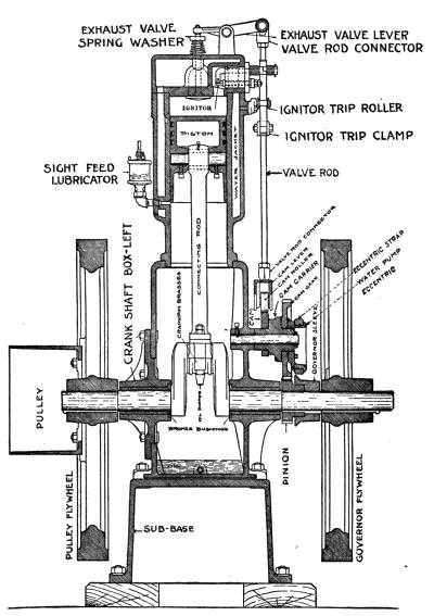
Fig. 151. Sectional view of gasoline engine.
[214]
269. Operating the Engine. One person should be responsible
for the care of an engine. Starting the engine is
usually too heavy work for most women. Since a man usually
starts a gas engine which the women are to use, it is more important
that they know how to stop the engine and to recognize
when it is not running properly. A cold engine can be
started easier if warmed with hot water.
Running an engine which is out of order may damage it seriously.
Have some one show you how to operate your engine.
Stop it when not running properly.
270. Points in Caring for Engine. The following are
points to keep in mind when operating an internal combustion
engine:
1) Black smoke issuing from the exhaust pipe means there
is not enough air in proportion to fuel.
2) When an engine misses more explosions than it should,
or backfires, the cause is likely to be too much air in the fuel.
3) If the mixture of fuel and air is in the proper proportion,
but there is too little of it, the engine will have no power.
4) Premature ignition may be caused by deposition of carbon
or soot on the walls of the cylinder; the compression
being too high for the fuel used; overheating of the piston, or
exhaust valve, or of some poorly-jacketed part.
5) Using too much or a poor quality of lubricating oil, or a
mixture too rich in fuel, causes deposition of carbon on the
cylinder.
6) The use of too much cylinder oil is indicated by a blue
smoke issuing from the exhaust.
7) Pre-ignition, or a bearing out of order, or the engine not
being securely fastened to its foundation, causes pounding.
[215]
8) Too much water in the oil used for fuel causes white
smoke to issue from the exhaust pipe. This may be caused
by a leaky jacket on gasoline engines.
9) Stop the engine by shutting off the supply of fuel. Open
the switch to the ignition system. Close the lubricators and
oil cups, and turn off the jacket water.
10) In cold weather, drain off the jacket water to prevent
freezing.
11) Always leave the engine clean and in order to start
again.
12) For safety, belts and wheels should be boxed in wherever
possible.
Fig. 151 should be studied closely for a better understanding
of the engine.
271. Generating Electricity for Homes. Water motors,
kerosene, gas and gasoline engines are the sources of
power commonly used to generate electricity for private
homes. A device for generating electricity is called a dynamo
(Fig. 152). The electricity generated is either used directly
while the engine is running, or it is stored in storage
batteries. From here it is conducted thru wires and used for
lighting, heating and turning motors to do work.
272. Batteries. Batteries are used mainly where a
small amount of current is needed, as on oil or gasoline engines,
to make the spark to ignite the gasoline or oil, and in
lighting gas and acetylene lamps, and for some door bells.
There are several kinds of batteries, as liquid, dry-cell and
storage.
273. Liquid Batteries. In liquid batteries, electric current
is generated by means of direct chemical action between[216]
an acid and two other substances, one more easily attacked by
the acid than the other (Fig. 153), such as zinc and copper.
This forms a simple cell, one form of primary battery. When
the chemicals and metals in a primary battery are exhausted,
they can be replaced with new metal or solution.
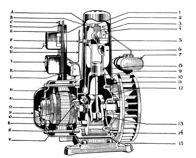
Fig. 152. Electric generator.
274. A Dry-Cell Battery. A dry-cell is another form of
battery. In these, the moisture of the acid substance is absorbed
by some material like plaster-of-Paris flour or blotting
paper, so that it can act on the metals or carbon in the cell and
still make a cell easily transportable. The absorbed moisture
in dry cells slowly evaporates, and then they become worthless.
These batteries are usually thrown away after they
have been used and have ceased to generate electricity.
275. Storage Batteries. Storage batteries differ from
primary batteries in that current must be supplied to them[217]
from some outside source, such as a dynamo. They can be
recharged again after the current in them has been used
(Fig. 154).
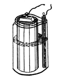
Fig. 153. Primary battery.
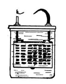
Fig. 154. Storage battery.
————
The engines for private homes where a light plant is used
are adjusted to charge batteries at the proper rate—but the
owner should charge these batteries at regular intervals.
They can be charged only by direct current.
Never allow the storage battery to run down to a voltage
lower than 1.15 per cell. This reading is taken from the voltmeter
supplied with the plant.
Storage batteries should be tested by a hydrometer for the
specific gravity of the electrolyte or liquids in them. Instructions
for this and for correcting the specific gravity accompany
the plant. Take care to preserve them.
Dynamos for home use are almost automatic. Run the
dynamo to renew the batteries when using electric irons or
other devices calling for more current than the lighting fixtures.
Each plant is designed to carry a certain load of
equipment. Exceeding this, damages the plant.
Place electric motors and dynamos in a dry, cool, clean
place.
[218]
276. Some Uses for Electric Motors. Motors are now
used on sewing machines, washing machines, dish washers,
vacuum cleaners, wringers, fans, refrigerating systems, pumps,
grinders, freezers, churns and separators. They are made
either for direct or alternating current. When purchasing a
motor, be sure to designate the type of current with which it is
to be used. Select motors of the right size to operate the machine.
It costs more to operate a large motor on a small device
than a small motor.
277. Definition Tables. A British thermal unit is the
amount of heat required to warm one pound of water one degree
Fahrenheit.
The flash point of an oil is that temperature at which it will
form an inflammable vapor. The accompanying table shows
amount of heat generated from a number of sources.
The total heat in a gallon of kerosene is greater than that in
a gallon of gasoline because the kerosene is heavier than the
gasoline. A gallon of gasoline will give on an average but
about five-sixths as much total heat as a gallon of kerosene.
This is approximately true, whether the heaviest grades of
kerosene are compared with the heaviest grades of gasoline, or
the lightest grade of kerosene is compared with the lightest
grade of gasoline.
Distillate is the refuse left from the distillation of petroleum.
The flash point of kerosene may be between 70 and 150 degrees
Fahrenheit, depending upon the grade. For illuminating
purposes, do not use kerosene with the flash point lower
than 120 degrees Fahrenheit.
The flash point of gasoline is 10 to 20 degrees Fahrenheit;[219]
that is, gasoline will form an imflammable vapor at temperatures
as low as this.
Between 60 and 70 per cent of the common fuels are utilized
in the generation of steam for heating purposes.
TABLE SHOWING GENERATION OF HEAT
| |
| Amount |
Fuel |
B. T. U |
| 1 lb. |
Anthracite coal |
13,200 |
- |
13,900 |
| 1 lb. |
Bituminous coal |
12,000 |
- |
15,000 |
| 1 lb. |
Lignite coal |
8,500 |
- |
11,400 |
| 1 lb. |
Wood |
8,200 |
- |
9,200 |
| 1 cu. ft. |
Natural gas |
900 |
- |
1,000 |
| 1 cu. ft. |
Illuminating gas |
500 |
- |
600 |
| 1 lb. |
Kerosene |
18,000 |
| 1 lb. |
Alcohol |
12,000 |
| 1 lb. |
Gasoline |
19,000 |
| 1 K.W.-hr. |
Electricity |
3,400 |
| |
*One pound ice in being melted will absorb 144 B. T. U.
[220]
CHAPTER XXXIX
Gas Plants
278. Gasoline-Gas Plants. Gasoline-gas plants are devices
for generating gas from gasoline. The gas is a mixture
of air and gasoline vapor. It is made by air being forced thru
gasoline. There are small plants which can be installed in
private homes (Fig. 155). Gasoline vaporizes at ordinary
temperature. The vapor or gas produced can be used for
heating, lighting and running gas engines.
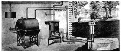
Fig. 155. Gasoline gas plant.
One gallon of gasoline, when entirely vaporized, produces
about thirty-two cubic feet of gas. Its heating power depends
upon the character of the gasoline utilized and the temperature
at which it is kept during vaporization.
The plant is a device for forcing air thru the gasoline to
make it vaporize as fast as wanted. Combined with the carburetor
is a storage tank for the gas. A weight, or water
motor, furnishes the power most commonly used in forcing the[221]
air thru the gasoline and forms a part of the plant. Air cannot
flow thru the gasoline when the storage tank is full of gas so
that the power is only in operation when the gas is being used
or the tank is not quite full.
279. Acetylene-Gas Plant. Acetylene is often used in
rural homes when gas or electricity are not available. The
operation of the plant often has to be attended to by a member
of the family. A capable woman can do this, but she must
be careful and must thoroly understand the plant (Fig. 156).
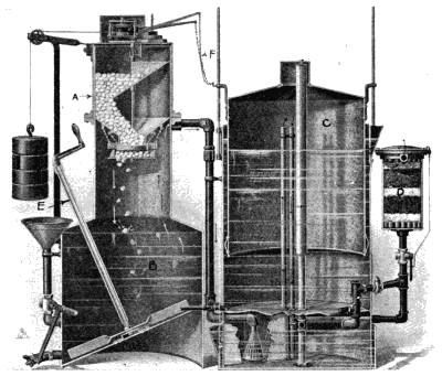
Fig. 156. Acetylene gas plant.
The materials used in making acetylene are calcium carbide
and water. Calcium carbide (A, Fig. 156) is made from lime[222]
and coke fused together in an electrical furnace. It must be
kept stored in a dry place.
The plants for making acetylene are inexpensive enough to
be installed in individual homes of moderate means. Calcium
carbide for making the gas can be transported without difficulty.
There are two types of machines. In one the water drips
on the carbide; in the other, the more common type, the carbide
is dropped into the water. As soon as the carbide
touches the water, it gives off acetylene gas. The gas is
caught in and fills a bell above the water. As it fills the bell,
it raises it, and when the bell reaches a certain height, it trips
a lever to the door which lets in the carbide and closes it.
When the gas is used, the bell goes down and, passing the
lever, opens the door to let in a small amount of carbide.
Improvements have been made in the plants and in installing
them until there is less danger from explosions than formerly.
Great care should be taken in operating them to
avoid accidents. Since the gas is highly explosive, fire,
lighted lamps and cigars must be kept away from the vicinity
of all acetylene plants. Only one person should take the care
of the plant, the others should understand how.
280. Directions for Operating Acetylene Plant.
1) Charge by daylight—remove all residuum, and fill with
fresh water before adding any carbide.
2) Follow exact directions for the machine used in the order
directed.
281. Cautions to Be Observed in Using Acetylene Gas.
1) Do not apply a light to any opening that is not equipped
with a regular acetylene burner tip.
[223]
2) See that any workman repairing a generator first removes
carbide and drains all water out, and disconnects it
from piping and removes it to the open air, where he then fills
all compartments with water to force out gas before using
soldering irons.
3) An open light should never be permitted nearer than ten
feet from the generator. The generator should never be
nearer than fifteen to twenty feet from furnace or stove. Do
not hunt for gas leaks with a flame or light.
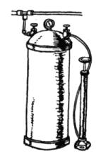
Fig. 157. Pressure
tank for
gas.
4) Do not use any artificial light except
electric light when cleaning or repairing generator,
or carry a lighted pipe or other fire
about it, even when empty.
5) If water in any chamber should freeze, do
not attempt to thaw it with anything but hot
water.
6) Keep the motor oiled. Oil once in six months.
282. Compressed Gases and Oils. Gases, such as Blau
gas, Pintsch gas, and prestolite gas which is compressed acetylene
gas, are compressed in strong tanks and sold for use in
lighting and light housekeeping. Gasoline and alcohol also
are occasionally stored in very strong tanks under enough
pressure to make them flow thru very small pipes to the point
where they are wanted for use. These are frequently used
for lighting isolated public buildings, such as rural schoolhouses.
As the gas or oil is used, the pressure diminishes. There is
usually a pump attached to the tank to pump in air in order
to keep up the pressure. The pump is similar to a bicycle
pump (Fig. 157).
[224]
Questions for Part X
1. What is the difference between the treadle and a motor-power
machine?
2. How is power secured from water in a water motor? Or what is
the source of power utilized by a water motor?
3. How do you determine the size of pulleys to use on the gasoline
engine and on the device it is to operate?
4. What are some indications that a gasoline engine or automobile
motor is not running properly?
5. What are the kinds of batteries, and to what uses is each best
suited?
6. Do batteries need care? If so, what care?
7. How is acetylene gas made? Describe the device for making it.
8. How is gas for household use made from gasoline?
[225]
PART XI
Measuring Devices
CHAPTER XL
Scales for Weighing
283. Equal-Arm Balances. Scales are devices for determining
the weight of objects. Balances—one form of
scales—are made of two arms of equal lengths and supplied
with discs of metal of a known weight to be placed on one arm
of the balance while the material to be weighed is put on the
other. When the two arms are in equilibrium, the weight of
the material is equal to the weight of the metal. Since the
weight of the metal is known, or can be determined, by adding
together the weights of the discs used, the weight of the material
is known to be the same.
284. Unequal-Arm Balances. Equal-arm balances are
not convenient for weighing large objects. For this reason,
scales are made with one arm of the balance much longer than
the other. The metal discs are then marked with the weight
of the material on the short arm which they can balance
when placed on the long arm. This is the usual form of
counter and household balances. On these scales is also a
weight which slides along the arm and is used to determine
weights smaller than five or ten pounds. The arm of the balance
is, therefore, marked at the point where this weight will
balance certain amounts of material, such as half ounces,
ounces and pounds.
[226]
285. Spring Scales. Spring scales depend on the action
of a spring, to which an indicating pointer is attached. When
there is no weight on the spring, the place to which the indicator
points is marked zero. When these scales are manufactured,
a pound weight is placed so that it pulls on the
spring and the indicator is pulled down to another place, and
this is marked one. Scales are thus marked for the number
of pounds they are to weigh. The spaces between the pounds
marked are divided into equal divisions, such as sixteenths
which indicates ounces. These scales cannot be relied on for
accuracy, for springs stretch or become weaker as they are
used. Avoirdupois is the weight in common use for marketing,
while many tables for calculating dietaries are in the
metric system.
The housewife can have her balances corrected for weighing
by the city or county sealer of weights and measures so that
she can ascertain whether or not her food purchases are correctly
weighed.
TABLE OF WEIGHTS
| Avoirdupois |
Metric |
| 16 oz.—1 pound |
1 milligram—1/1000 .001 gram |
| 100 lb.—1 hundred-weight |
1 centigram—1/100 .01 gram |
| 2000 lbs.—1 ton |
1 decigram—1/10 .1 gram |
| 0.035 oz.—1 gram (Metric system) |
Gram—1 gram |
| |
Dekagram—10 grams |
| Apothecaries |
Hectogram—100 grams |
| 27-11/32 grams—1 dram |
Kilogram—1000 grams |
| 16 drams—1 oz. |
[227]
CHAPTER XLI
Devices for Measuring Volume
286. Graduate and Measuring Cup. Graduate holding
up to four fluid ounces is helpful to use to check up liquids
bought in bottles. The standard measuring cup referred to
in modern cook books holds half a pint of liquid. It also
holds about sixteen level tablespoonfuls of dry material such
as sugar. The divisions on glass cups are less likely to be accurate
than on metal ones, as the bottom may be thick or thin
unless carefully made. In selecting a cup, see that the bottom
section is equal to the other sections.
1 cup = 2 gills = 1/2 pint = 16 tablespoons =
48 teaspoons = 8 fluid ounces.
1 cup is also 1/4 of a quart and about 4/17 of a
liter.
287. Tablespoons. Tablespoons vary in size. The size
chosen for measuring is the one in most common use and
holds about three level teaspoonfuls of material like sugar or
flour.
1 tablespoon = 4 drams of liquid = 3 teaspoons.
4 tablespoons = 1/4 cup = 2 fluid ounces.
288. Teaspoons. Teaspoons vary in size, but the spoon
in common use is the one understood as the measure in cookery.
It holds about one and one-third fluid drams.
289. Standard Measuring Spoons. Standard measuring
spoons in sets can be purchased at a very moderate[228]
price. They are particularly valuable for checking the capacity
of the spoons more commonly used.
290. Liquid and Cooking Measures.
1 teaspoonful = 1-1/3 fluid drams
3 teaspoonfuls = 1 tablespoonful= 4 drams
2 tablespoonfuls = 1 fluid ounce
1/2 cup = 1 gill
2 gills = 1 cupful = 8 fluid ounces
16 tablespoonfuls = 1 cupful
2 cupfuls = 1 pint
2 pints = 1 quart = 4 cupfuls
4 quarts = 1 gallon
4.23 cupfuls = 1 liter
1000 cubic centimeters = 1 liter
1.06 liquid quarts = liter
31-1/2 gallons = 1 barrel
1 milliliter = one-thousandth (.001) liter
1 centiliter = one-hundredth (.01) liter
1 deciliter = one-tenth (.1) liter
Liter = 1 liter
1 dekaliter = ten (10) liters
1 hectoliter = one hundred (100) liters
1 kiloliter = 1 thousand (1000) liters
291. Dry Measures. It is wise for a housewife to have a
set of dry measures, consisting of a pint, quart, gallon, peck
and half-bushel measure. A quart or gallon liquid measure
is not equal to the dry one. It holds less. The diameter of
dry measures should be as follows:
DIAMETERS OF DRY MEASURES
| Measure |
*Diameter |
| 1 pint |
4 inches |
| 1 quart |
5-3/8 inches |
| 2 quarts |
6-5/8 inches |
| 1/2 peck |
8-1/2 inches |
| 1 peck |
10-7/8 inches |
| 1 bushel |
13-3/4 inches |
*These diameters allow for proper heaping.
[229]
DRY MEASURE*
2 pints = 1 quart
8 quarts = 1 peck
4 pecks = 1 bushel
1 sack of flour = 24-1/2, 49 or 98 pounds
4 49-pound sacks of flour = 1 barrel
1 barrel of flour = usually 196 pounds
60 pounds of potatoes = usually 1 bushel
*State laws differ somewhat regarding the number of pounds
in a bushel of various fruits and vegetables.
292. Cubic, Square and Linear Measure.
CUBIC MEASURE
1728 cubic inches = 1 cubic foot
27 cubic feet = 1 cubic yard
128 cubic feet = 1 cord
SQUARE MEASURE
144 square inches = 1 square foot
9 square feet = 1 square yard
30-1/4 square yards = 1 square rod
160 square rods = 1 acre
640 acres = 1 square mile
LINEAR MEASURE
12 inches = 1 foot
3 feet = 1 yard
5280 feet = 1 mile
39.27 inches = 1 meter
METRIC MEASURES
Millimeter = one-thousandth (.001) meter
Centimeter = one-hundredth (.01) meter
Decimeter = one-tenth (.1) meter
Unitemeter = 1 meter
Dekameter = ten (10) meters
Hectometer = one hundred (100) meters
Kilometer = 1 thousand (1000) meters
[230]
CHAPTER XLII
Gas, Water, and Electric Meters
293. Different Kinds of Meters. The housewife has
need to be familiar with three kinds of meters—water, gas and
electric. These are devices for measuring water, gas or electric
current.
294. Construction of a Gas Meter. The interior of
one type of gas meter (Fig. 158) is somewhat like a water
wheel—the pressure of the gas pushes the wheel around.
Every time a compartment full of gas passes a certain point,
the gas flows out and the flange on the wheel trips a lever
which moves the hand of the dial ahead, thus counting the
emptying of the compartment. The gas in the compartment
back of this then moves to this place. The emptied compartment
is filled with more gas as it passes the inlet.
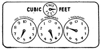
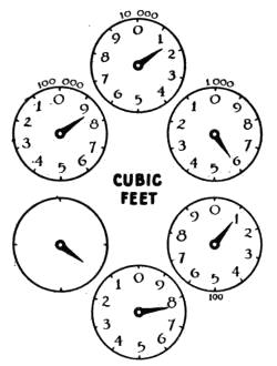
295. Reading the Gas Meter. A gas meter is a device
for measuring the number of cubic feet of gas which flows
thru a pipe. Small dials with the numbers from one to ten
and a hand for an indicator show the number of single feet,
tens of feet, and thousands of feet, which have passed thru[231]
the meter. The reading on any date is the total amount of
gas which has passed thru. To tell how much has passed
thru the meter during any period of time, take the reading of
the meter on the first date, as indicated in Fig. 158, and then
take the reading on the later date and subtract reading one
from reading two—the resulting figure is the amount of gas
passing thru the meter between
these two dates. When buying
gas, always keep the readings of
meters at the time when the gas
man takes them. Gas meters
often register more or less gas
than is actually consumed. Gas
companies are allowed a variation
or tolerance of one per cent fast
or slow, to two per cent fast or
slow. Gas is paid for at a stated
rate per thousand feet in most
places.
296. Water Meters. The water meter (Fig. 159) is a device
for measuring the number of gallons or cubic feet of
water which pass thru a pipe. The reading of the meter indicates
the total amount of water which has passed thru the
pipe since the meter was installed. Water is paid for, unless
purchased at a flat rate, at so many cents a thousand gallons
or thousand cubic feet. One cubic foot is called in commercial
transactions 7-1/2 gallons.
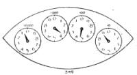
Fig. 160. Electric meter.
297. Prepayment Meters. Prepayment meters are devices
which will permit a certain amount of gas or water, as
the case may be, to pass thru a pipe, and after this amount is[232]
used up, the pipe is automatically closed so that no more
flows until more money is put into the meter. The weight of
the coin works the valve.
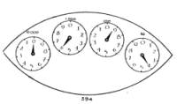
Fig. 160-a. Electric meter showing
different readings.
298. The Electric Meter. Electricity is usually purchased
by the kilowatt hour, and measured by the watt-hour
meter (Fig. 160). This
measures the current passing
thru it, and the number
of kilowatt-hours is shown
by the indicators on the
little dials. Start from left
and read the number on
the dial, such as in the illustration, 3 hundreds 4 tens 9 units,
making 349 kilowatt-hours; the total kilowatt-hours used
since the meter was installed.
To find the number
used between two dates,
take the reading of the
meter on the first date and
subtract it from the reading
on the second date. The
difference is the amount
used during the period. Good business women keep records
of the readings of their meters. Care must be taken to read
the meter correctly. The hand next higher than the one
below may read too high. The higher hand may, if out of
alignment, pass the figure when the lower hand approaches
the ninth point in its dial, this causing the person to read the
figures one, ten, hundred or thousand units too much.
(Fig. 160-a.)
[233]
CHAPTER XLIII
Thermometers and Thermostats
299. Mercury Thermometers. There are two kinds
of thermometers in use—the Fahrenheit and the Centigrade.
Since the thermometer is used now in cooking, the housewife
often has to meet the problem of translating temperatures
from one to the other.
The centigrade thermometer is marked on the assumption
that the temperatures of boiling water and freezing water are
constantly the same. The boiling point is marked 100, and
the freezing point 0. The space in between is marked into
even divisions and numbered 1 to 99.
The Fahrenheit thermometer was made on the assumption
that a mixture of ice and salt was the coldest temperature
that could be reached, so this temperature of a certain proportion
of ice and salt was marked zero.
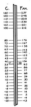
Fig. 161. Comparison
of Centigrade
and Fahrenheit.
The hundred point was given to what was supposed to be
the normal body temperature. The intervening spaces were
marked into equal divisions, and these divisions were carried
below 0 degree and above 100 degrees. The boiling temperature
of water came at 212 degrees Fahrenheit, and the
freezing point at 32 degrees. This makes 180 degrees difference
between thawing and freezing and boiling. So 100 degrees
Centigrade equal 180 degrees Fahrenheit. Therefore,
1 degree Centigrade equals 9/5 degrees Fahrenheit, and 1 degree
Fahrenheit equals 5/9 degree Centigrade.
[234]
For example, if 40 degrees Centigrade is to be translated
into Fahrenheit degrees, first multiply 40 by 9 = 360, then
divide by 5 = 72, and add 32, because 0 degree Centigrade is
the same as 32 degrees Fahrenheit, and the result is 104 degrees
Fahrenheit equal 40 degrees Centigrade. If 41 degrees
Fahrenheit is to be translated into Centigrade
degrees, first subtract 32 from 41 =
9, then multiply by 5 = 45, and divide by
9, and the result is 5 degrees Centigrade = 41
degrees Fahrenheit. Fig. 161 is a diagram
showing relative readings of Fahrenheit and
Centigrade thermometers.
300. Oven Thermometer. Some oven
thermometers depend on the expansion of
metal to indicate the temperature. A hand
on the clock-like face of these indicators
shows the degree of heat. Few of these give
the actual temperature, but they do indicate
a slow, a moderate and a hot oven.
301. Maximum Thermometers. A
maximum thermometer is one in which the
mercury rises to register the maximum
amount of heat to which it has been subjected. It stays at
this height when the temperature falls, until it is shaken
back.
It is sometimes used in ovens to ascertain the temperature
they have reached before the oven door is opened.
[235]
TABLE OF TEMPERATURES USEFUL TO HOUSEKEEPERS
| OVEN TEMPERATURES |
| |
Fah. |
Cent. |
| Slow oven |
250 |
- |
350 |
121 |
- |
177 |
| Moderate |
350 |
- |
400 |
177 |
- |
204 |
| Hot or quick |
400 |
- |
450 |
204 |
- |
232 |
| Very hot |
450 |
- |
550 |
232 |
- |
287 |
| SYRUPS |
| |
Fah. |
Cent. |
| Thin |
219 |
- |
|
104 |
- |
|
| Medium—fondant |
236 |
- |
240 |
113 |
- |
115 |
| Thick—fudge |
|
- |
240 |
115 |
- |
| Heavy—taffy |
- |
300 |
149 |
- |
| Clear brittle |
- |
310 |
150 |
- |
| Carmel almond and nut |
- |
315 |
157 |
- |
| MISCELLANEOUS |
| |
Fah. |
Cent. |
| Incubators |
|
|
103 |
39 |
. |
4 |
| Body temperature |
98 |
- |
99 |
37 |
| Room temperature |
|
- |
86 |
20 |
- |
30 |
| Refrigerator temperature |
44 |
- |
59 |
5 |
- |
15 |
| Churning |
52 |
- |
62 |
11 |
- |
17 |
| Growth of bacteria retarded |
35 |
- |
70 |
|
| Growth of bacteria most rapid |
70 |
- |
100 |
| Most bacteria are killed |
212 |
| Downward, markedly. Growth of bacteria retarded |
45 |
| |
302. Thermostats. Thermostats are devices which
open or close valves or dampers in order to keep rooms, boilers,
ovens, incubators, etc., at an even temperature. All
metals expand on being heated, and contract on being cooled.[236]
Some expand more than others. Two materials which expand
at different rates are frequently used in making thermostats.
Any certain temperature causes a given piece of
metal to expand to a certain size, or to contract on cooling to a
different size. Some thermostats are made of a straight rod
of metal like copper which expands more than iron when
heated. The rod is so placed that when cool it will allow fuel
like gas or oil to pass thru a pipe, and when heated, it will
expand enough to close the pipe, shutting off the fuel. They
are placed so that they close the pipe at the temperature desired
for an oven or supply of hot water.
Other thermostats are more complicated, as the expanding
metal moves a series of levers. These thermostats are used
to regulate dampers on coal and wood furnaces, when they are
placed in the rooms to be heated. They are often used on
other devices, such as incubators.
Still others control an electric current. When the metal
expands, it closes the circuit, causing the electricity to do the
work desired. When it contracts, it opens the circuit. Thermostats
can be set to do work at different temperatures.
These are sometimes attached to clocks which, with a device
similar to the alarm, will change the indicator of the
thermostat so as to set it from one temperature to another at
a stated time for which the clock is set and turn it back at
another hour.
[237]
CHAPTER XLIV
Hydrometers and Barometers
303. Hydrometer. A hydrometer is used in gaging the
density of liquid. This instrument consists of a closed glass
tube which is enlarged at the lower end and filled with some
heavy material like mercury or shot, to keep it in an upright
position when in liquids.
The tube or stem contains a paper on which divisions called
degrees are marked. The 0 mark is usually the point reached
by the surface of distilled water when the hydrometer is
placed in this liquid. The less the density of the liquid, the
lower the hydrometer sinks, for it displaces an amount of
liquid equal to its own weight. The density of the liquid
then can be determined by observing the mark to which it
sinks. Specific-gravity hydrometers used in the household
show the ratio of the weight of a given volume of liquid to the
weight of the same volume of water at a definite temperature.
Arbitrary scale hydrometers are used to indicate the concentration
or strength of syrup, brines or milk. These are defined
as lactometers and Baume hydrometers. A brine hydrometer
is called a saltometer, and a syrup gage a sacchrometer.
A jellometer, especially for making jelly, is
sometimes used instead of a sacchrometer. The scale on this
tells how much sugar to use in proportion to the amount of
solids in the fruit juice without having to refer to a table.
Some hydrometers are constant-volume hydrometers, and on
these weights are placed always, to sink the hydrometer to
the same depth in the liquid.
[238]
TABLES FOR BRIX AND BALLING HYDROMETERS WHEN
USED AT 20° C.*
| |
Reading on the Hydrometer
Degrees |
Sugar to a Quart of Fruit Juice to Make Jelly |
| Pounds |
Ounces |
| 5 |
. |
|
|
8 |
. |
| 5 |
. |
5 |
9 |
. |
| 6 |
. |
0 |
9 |
. |
6 |
| 6 |
. |
5 |
10 |
. |
7 |
| 7 |
. |
0 |
11 |
. |
6 |
| 7 |
. |
5 |
12 |
. |
4 |
| 8 |
. |
0 |
13 |
. |
2 |
| 8 |
. |
5 |
14 |
. |
1 |
| 9 |
. |
0 |
15 |
. |
0 |
| 9 |
. |
5 |
15 |
. |
8 |
| 10 |
. |
0 |
1. |
7 |
. |
0 |
| |
When the reading for the fruit juice is determined the table shows how much sugar is
used for juice of that specific gravity.
TABLE SHOWING AMOUNT OF SUGAR PER GALLON
| |
Reading on the Hydrometer
Degrees |
Sugar to a Gallon of Water |
| Pounds |
Ounces |
| 0 |
. |
|
|
0 |
. |
0 |
| 5 |
. |
7 |
. |
0 |
| 10 |
. |
14 |
. |
8 |
| 15 |
. |
1 |
. |
|
7 |
. |
5 |
| 20 |
. |
1 |
. |
14 |
. |
75 |
| 25 |
. |
2 |
. |
12 |
. |
5 |
| 30 |
. |
3 |
. |
9 |
. |
0 |
| 35 |
. |
4 |
. |
7 |
. |
75 |
| 40 |
. |
5 |
. |
8 |
. |
75 |
| 45 |
. |
6 |
. |
13 |
. |
00 |
| 50 |
. |
8 |
. |
5 |
. |
25 |
| 55 |
. |
10 |
. |
4 |
. |
00 |
| 60 |
. |
12 |
. |
8 |
. |
0 |
| |
[239]
In the second table the readings show the specific gravity
of the syrup, and from that may be ascertained the proportion
of sugar to a gallon of water in it.
A 250 cc. cylinder, or other tall vessel deep enough to float
the sacchrometer, is suitable for making the measurements.
Be sure to have the eye on the level of the liquid when making
the readings. If no sugar is in the water, the reading on the
hydrometer will be near zero. If there is sugar in the proportion
of seven ounces to a gallon of water, the reading will be at
the line marked 5.
SYRUPS FOR CANNING
| Berries |
—30 degrees, or 3½ pounds of sugar to 1 gallon of water |
| Sweet cherries |
—30 degrees |
| Sour cherries |
—40 degrees |
| Peaches |
—30 to 40 degrees |
| Pears |
—20 to 30 degrees |
| Plums |
—40 degrees |
304. Hygroscopes. Hygroscopes are devices for measuring
humidity. Forty-five to sixty per cent
humidity is desirable in a house. This means
forty-five to sixty per cent as much water as
the air is capable of taking up at room temperature.
Cold air is usually dryer than
warmer air because cold air cannot take up as
much humidity as warm air. This is analogous
to the fact that warm water will dissolve
more of some salts or of sugar than cold water.
305. Barometers. Barometers (Fig. 162) are devices
which show changes in pressure and currents of air. Changes
in the barometer usually indicate changes in the weather, and[240]
thus they are of interest to all persons. A decided fall in the
mercury of a barometer usually precedes foul weather, while a
rise indicates the approach of fair weather. When the pressure
is low in any locality, air begins to rush toward that
point as it would to fill a vacuum. So a fall in the barometer
precedes the coming of a high wind or a rainstorm. A rise in
the barometer precedes a calm, and since most rain is accompanied
with wind, the calm is a time of fair weather.
[241]
INDEX
A
Absorption of heat and light, 84, 85, 108
Acetylene, 30, 49, 81, 91, 92, 145, 221, 222, 223
Acids, 155, 156, 157, 159, 216
Acre, 229
Adjustment of burners, stove, 24, 29, 30, 32, 34, 41, 49, 78, 79, 80
Air, for circulation, 57, 76, 101, 102, 103, 111, 198
dead or stagnant, 63, 102
for combustion, 16, 29, 31, 38, 39, 48, 66, 88, 93, 214
for evaporation, 105, 176, 220, 221
for heating, 19, 55, 60, 61, 62, 63, 73, 75, 79
in radiator, 67, 68, 70
mixer, 23, 24, 25, 33, 77, 96, 144
moisture, 239
for pressure, 97, 112, 113, 114, 175, 176, 184
shaft, 57
whistling, 56
Alcohol, 47, 48, 89, 96, 97, 98, 145, 223
Alkalies, 155, 157
Alternating current, 110
Aluminum, 78, 156, 157, 158, 171, 172
Ammonia, 108, 138
Ampere, 82
Andiron, 74
Anthracite coal, 219
Asbestos, 32, 66, 77, 81
Ash chute, 22
Ashes, 20, 57, 66, 74, 75, 76
Automobile, 192
B
Back-fire, 192, 214
Bacteria, 100, 101, 127
Balances, 225
Balling hydrometer, 238
Barometer, 239, 240
Barrel, 167, 228, 229
Basin, catch, 127
Battery, 192, 193, 194, 215, 216
Baume hydrometer, 237
Bearing, 152
Beater, 165
Bell for storing gases, 222
Bellows, 148, 149
Belts, 136, 137, 141, 186, 215
Bituminous coal, 219
Blau gas, 223
Bobbin, 187, 188, 189
Boiler, 64, 69, 71, 73, 132, 133, 156
Booster, 119
Bracket, curtain, 185
Brine for cooling, 108
British thermal unit, 218, 219
Brix hydrometer, 238
Broiler, 26
Brush, 147, 149, 150, 152
Bunsen burner, 77, 78, 81
Burner, 48, 96, 119, 141, 145, 198
gas, 23, 25, 27, 29, 77, 78, 88, 91, 144
kerosene, 32, 33, 36, 37, 40, 80, 94
Burning back, 27, 89, 90, 91
Burr grinder, 162
Bushel, 228, 229
C
Calcium carbide, 221, 222, 223
Candle power, 84, 89, 91, 95
Canned heat, 48
Canner, 172, 173
Can sealer, 175
Capillary attraction, 47, 48, 93, 106
Carbolic acid, 126
Carbon, 82, 83, 84, 214
Carbon dioxide, 67, 108
Carburetor, 29, 192, 220
Carpet sweeper, 147, 148, 150
Cast aluminum, 156
Cast iron, 155, 156
Catch basin, 127
Centigrade thermometer, 233, 234
Centigram, 226
Centimeter, 228, 229
Centiliter, 228
Centrifugal dryer, 138, 139, 140
force, 139
[242]washer, 135, 136
Cerium, 88
Cesspool, 124
Charcoal filter, 114
Chain stitch, 186
Cherry stoner, 161, 162
Check valve, 71, 183
Chimney, 18, 31, 33, 57, 59, 74, 75, 80, 93, 94, 111
Chloride of lime, 126
Choker, 192
Chopper, 162, 163
Churns, 165, 167, 235
Cistern, 114
Clamp, 138
Cleaning, 25, 35, 127, 172
Cleaning equipment, 147, 148, 149, 150, 152, 153
Clinkers, 76
Clock, 236
Clutch, 192
Coal, 20, 28, 66, 76
Coffee mill, 162
pot, 167, 168
Cog wheels, 165
Coils, 64, 78, 80
Coke, 222
Cold-process gasoline-gas, 29, 91, 145
Color and illumination, 84
Compressed-air pump, 113, 115, 117
Combustion, 16, 17, 23, 24, 58, 66, 74, 76, 77
Conductivity of materials, 156, 157, 158
Contraction of materials, 235
Cookers, 50, 51, 55, 56
Coolers, 105, 106, 108, 109
Copper, 158, 216, 236
Crank, 163
Cream separator, 178, 179
Cubic measure, 229
Cup, measuring, 227, 228
Current, electric, 42, 46, 80, 83, 86, 110, 143, 144, 215, 218, 232
Curtain roller, 185
Cylinder, 112, 113, 211
washer, 133
D
Dampers, 16, 17, 18, 19, 20, 22, 58, 61, 66, 74, 75, 197, 198, 235, 236
Decomposition of sewage, 124, 125, 127
Degree, 233, 234
Dekagram, 226
Dekaliter, 228
Dekameter, 229
Dermax, 206
Density of liquids, 237
Direct current, 110
Direct lighting, 85
Dish-washer, 170, 171
Disinfectant, 126, 200
Distillate, 40, 218
Dolly washer, 134
Doors, 103, 183, 184, 185, 215
Drafts, 16, 17, 18, 19, 57, 58, 59, 74
Drain, 103, 104, 122, 138
Dram, 226, 228
Drip pipe, 102, 103
Drip sheet, 25
Dryer, 171, 176
Dry-cleaning equipment, 140
Dry-cell battery, 215, 216
Dulling of edges, 159, 163
Dumbwaiters, 183
Dust, 76, 78, 80, 148, 150
Dynamo, 215, 216
E
Earthenware, 107, 156
Egg tester, 201
Electric appliances, 42, 44, 46, 81
heating, 42, 43, 80, 119
measurements, 43, 82, 230, 232
Electric motors, 217
Electricity, 215, 219
Electrolyte, 217
Enameled ware, 157
Engine, gasoline, 137, 212
Evaporation, 67, 105, 106, 140
Exhaust pipe, 212, 214
Expansion of materials, 108, 234, 235
tank, 66, 67, 120
[243]valve, 70
Explosions, prevented, 25, 35, 37, 39, 69
utilized, 192, 214, 222
Extractor, 139
F
Fahrenheit thermometer, 233, 234
Fan, 110, 148, 177
Fastener, door, 184
Faucet, 109, 114, 116, 119, 120, 122
Feed plate, 187, 188, 189, 207
Filament for lamp, 83
Filter, water, 114, 116, 168
Fire, 18, 19, 34, 41, 66, 75
Fireless cooker, 50, 51
Fireplace, 74, 75
Fire-pot, 20, 57, 58, 65, 76
Flame, 23, 35, 38
Flame, blue, 31, 38, 49, 96
illuminating, 77, 78, 88, 89, 93, 94
Flash point, 218
Flat-iron, 142
Float for flushing tank, 129, 130
Flue, 66, 77
Force pump, 113, 117, 119
Freezer, 166, 167
Freezing, 68, 112, 126, 166, 233
Friction, danger from, 140
Fuel, 16, 58, 65, 76, 88, 119
economical use of, 19, 20, 28, 59, 66
Funnel, 133, 167, 168
Furnace, 57, 62, 63, 64, 75, 222
Fuses, 43, 46, 86, 144
G
Gage, 67, 69, 70, 73, 117
Gage, steam, 72, 173
Gallon, 228
Gas, 26, 34, 35, 36, 37, 38, 40, 58, 88, 108, 192, 199, 214, 215, 219, 221, 230
burners, 77, 79, 90, 144
consumption, 23, 28, 29, 66
formation, 96, 97, 98
kinds of, 29, 91, 220, 222, 223
Gasoline, 89, 97, 99, 140, 219, 223
burner, 37, 96
engine, 119, 137, 212, 215
Gasoline-gas, 29, 37, 91, 220
Gears, 192
Generation of heat and gas, 219, 220
Generator, 96, 97, 145, 223
Gill, 227, 228
Glass utensils, 156, 157, 158
Graduate, 227
Gram, 226
Granite ware, 156, 157
Grate, 16, 58, 65, 74, 76
Grater, 160
Gravity lamp, 96
Gravity, specific, 217, 237, 239
Grinder, 159, 162
H
Heat, 29, 48, 89, 156, 158, 218
production of, 42, 140, 143, 200, 219
use of, 45, 50, 57, 69, 78, 80, 140, 143, 176
Heater, 65, 77, 79, 80, 81, 118, 119, 135, 141, 143, 196, 197
Hectograph, 205, 206
Hectoliter, 228
Hectometer, 229
Hinge, 184, 185
Homogenizer, 180
Horse power, 210
Hot-water furnace, 64
Hot-water tank, 117
Humidity, 239
Hundred-weight, 226
Hydrometer, 217, 237, 238, 239
Hygroscope, 239
I
Ice, 100, 101, 102, 103, 104, 166, 219
Iceless refrigerator, 105, 106
Incubator, 196, 201, 235
adjustment of, 199
Ignition of gas, 140, 214, 215
Illumination, 28, 77, 78, 82, 84, 85, 88, 218, 219
Inch, 228, 229
Ink, 205, 208
[244]Insulation, 19, 46, 50, 55, 57, 66, 102
Iron, 155, 156, 158, 236
Ironing board, 144
Irons, 142, 144, 145, 146
J
Jars, fruit, 176
Jellometer, 237
Jugs, 107
K
Kerosene lamps, 93, 95
oil, 28, 138, 219
stoves, 31, 79, 80
Kisselguhr filter, 114
Keyboard, 202, 204
Kilogram, 226
Kiloliter, 228
Kilometer, 229
Kilowatt, 82, 232
Kneading machine, 165
Knives, 159, 163, 196
Knocking, cause of, 71, 214
L
Lard press, 163
Lamp, adjusting burners, 89, 90, 93, 94
electric, 82, 83, 84, 87
gas or oil, 91, 92, 94, 95, 96, 196, 198, 199, 215
Laundry tubs, 127
Lawn mower, 195
Lava tip, 89
Leather, preventing shrinking of, 112
Lever, 72, 154, 163, 190, 236
Light, 83, 84, 85, 86, 98
Lights, 82, 88, 98
Lighters, 28, 91, 215
Lighting, lamps, 89, 90, 94, 95
stoves, 25, 27, 33, 34, 37, 38, 78, 79, 80
Lighting plants, 86, 114
Lime, 221
Lining refrigerator, 101
Lignite coal, 219
Liquify, sewage, 124, 125
Liquids, 237
Liter, 227, 228
Locomotive washer, 135
Logs, gas, 78
Lock-stitch, 186, 188
Lubrication, 193
M
Mangles, 141
Mantles for lamps, 88, 89, 90, 91, 95, 98
Manufactured gas, 78, 89, 91
Maximum thermometers, 234
Mazda lamps, 82, 83, 84
Measurements, 225
Melting ice, 103
Metal, conductivity of, 156, 158
Meter, 229, 230, 231, 232
Microbes, septic, 126
Mile, 229
Milligram, 226
Milliliter, 228
Millimeter, 226
Mimeograph, 206
Mixer, 165
Moisture, 200, 239
Mop wringer, 154
Motor, 108, 110, 133, 150, 186, 192, 209
care of, 214, 217
water, 137, 209, 210, 211, 220
Mower, 196
Multigraph, 206, 208
N
Natural gas, 30, 89, 219
Needle, 187, 188, 191
Nickel, 158
Nozzle, 148, 149
O
Oil, 31, 93, 110, 200, 214, 218, 223
Oil cups, 33, 35
Oscillating washer, 134, 135
Ounce, 226, 228
Oven, 19, 20, 26, 27, 42, 235
Overflow, 67, 119, 120, 122, 130
P
Packing, 112, 122
Pans, 155, 156
Parers, 159, 160
Peck, 228, 229
Percolator, 168
Pet cock, 174, 175
[245]Pilot light, 26, 27, 119
Pint, 227, 228, 229
Pintsch gas, 223
Pipe, stove, 58, 60, 61, 62
water or steam, 64, 66, 69, 70, 72
Pipes, 67, 78, 102, 103
Pipeless furnace, 63
Piston, 112, 148, 211, 214
Pivot, 166, 167, 209
Plate, mower, 195
Plug, electric, 143, 144
Plumber's pump, 123
Plumbing system, 115, 117
Pneumatic hinge, 184
lamp, 96
Porcelain filter, 114
Pots, 155, 156, 167, 168
Pound, 72, 226
Power, 82, 209, 210, 214
Prepayment meter, 231
Press, 163
Pressure, 72, 73, 78, 79, 82, 117, 137, 138, 146, 164, 171, 173, 209, 223
Pressure, air, 96, 97, 176
gage, 69, 117
Prestolite gas, 223
Pulley, 137, 185, 212
Pump, 108, 112, 113, 117, 123, 148, 168, 169, 209, 223
Q
Quart, 227, 228
R
Rack for canner, 172
Radiation of heat, 57, 61, 62, 79
Radiator, 64, 68, 69, 70, 71
Radiator, gas, 77, 78, 79
Reading meters, 231, 232, 238, 239
Reflector, 77, 78, 80, 81
Refrigerating plant, 108
Refrigeration, principles of, 100
Refrigerator, 100, 101, 102, 103, 104, 105
Register, 60, 62, 75
Regulation, heat and pressure, 20, 60, 66, 70, 72, 73
Regulation of stoves, 24, 43, 44, 48
Regulator, temperature, 198, 199
Reservoir, 18
Resistance produces heat, 143
Revolutions of motor wheels, 137
Ribbon, typewriter, 203, 208
Roller, 138, 141, 142, 154, 162
Rotary washer, 134
S
Saccrometer, 237, 239
Sack, flour, 229
Sadirons, 142
Safety devices, 45, 56, 71
Safety valve, 72, 79, 117, 119, 174, 175
Salt, 157, 166
Saltometer, 237
Scales, 226
Scissors, 196
Screw, 163
Seal for sewer pipe, 128
Seeder, 159, 161
Semi-indirect light, 86
Separators, cream, 178
Septic tank, 124, 125, 127
Sewage, 124, 125, 126
Sewer, 124, 127, 128
Sewing machine, 186, 191, 209
Shaft, 159, 186, 187, 202, 204, 209
cold-air, 57, 60, 63
Shears, 196
Sheet iron, 155, 156
Shutter, furnace pipe, 60
Shuttle, sewing machine, 188
Silicon, 158
Silver, 158, 171
Simmerer, 30
Siphon, 125, 129
Slicer, 159, 163
Smoke, 16, 20, 32, 34, 36, 57, 59, 66, 73, 74, 80, 89, 146, 214, 215, 246
Socket, electrical, 143
Soot, 17, 20, 32, 39, 66, 75, 78, 214
Sparks, electric, 110, 144
Specific gravity, 217, 237, 239
heat, 156, 158
Speed by use of wheels, 165, 212
Spiral, 163
Spoons, 157, 158, 227, 228
Spring, 59, 184, 185, 226
pulley, 183
Steam, 71, 79, 111, 133, 175, 219
[246]pressure, 69, 70, 72, 73, 174, 175
Steam
cooker, 56
valves and gages, 70, 72, 73, 173
Steel for cooking, 155
Stencil, 206
Stitch, 187, 188, 189, 191
Stones, fireless cooker, 50, 54
Stoner, 161
Storage tank, 113, 220
Storage battery, 215, 216, 217
Stove, 37, 47, 48, 49, 57, 58, 63, 65, 70
electric, 42, 44, 157
gas, 23 to 30, 144
heating, 75, 76, 78, 80, 141
Stove, wood and coal, 15, 22
Stoves, care of, 31, 34, 41, 44, 76, 78
Stuffer, 163, 164
Suction pump, 112, 113
washer, 132, 133, 169
Sweeper, carpet, 147, 148, 150
Switch, ignition, 192
Syrup, temperatures of, 235
T
Tables, 85, 158, 219, 226, 227, 228, 229, 235, 238
Tablespoons, 227, 228
Tank, 30, 31, 35, 37, 39, 40, 64, 67, 96, 146, 220, 223
septic, 124, 125, 126, 127
water, 107, 109, 113, 117, 119, 128, 129, 130
Teaspoon, 227, 228
Temperature, 20, 51, 73, 101, 103, 105, 173, 196, 198, 200, 206, 220, 233, 236
Tempering of metal, 156
Tension, 187, 188, 189
Tester, egg, 201
Thawing, 233
Thermal unit, 218
Thermometer, 197, 199, 233, 234
Thermostat, 197, 198, 199, 200, 235, 236
Thorium, 88
Thread, 187, 188
Throttle, 192
Thumb-screw, 138, 174
Time for cooking food, 54
Timer, 193
Tin, 155, 156, 158
Ton, 226
Trap, 122, 128
Trays, 176, 197, 200
Treadle, 186, 209
Tungsten, 82, 83, 158
Type, 203, 204, 208
Typewriter, 202, 203, 206
U
Utensils for cooking, 44, 155, 156
V
Vacuum, 112, 176, 240
cleaner, 147, 148
Valve, 25, 26, 29, 33, 37, 52, 68, 69, 70, 71, 72, 90, 112, 113, 119, 120, 122, 129, 130, 145, 174, 183, 197, 211, 232, 235
Vapor, 40, 41, 145
Vent, radiator, 68
Ventilators, 110, 111, 197, 198, 200
Volt, 82
Voltage, 86, 110, 144, 217
W
Warping, 76
Washboard, 134
Wash boiler, 172
Washers for valves, etc., 120
Washing equipment, care of, 136, 138, 139, 141, 142
Washing machines, 132, 133, 135, 136, 209
Waste, 76, 124
Water, 67, 102, 106
closets, 128
coolers, 105, 108
filters, 114
for cooling, 107, 215
for furnaces, 64, 66, 67, 68, 70, 71, 72, 81
heater, 118, 119
meter, 230
motors, 137, 209, 210, 211, 220
tanks, 119
-bath canner, 173
[247]-seal canner, 173
Watt, 82, 84
Weight, 220, 226
Wells, 113, 125
Wheels, 137, 165, 211, 230
Whey separator, 180
Whistle, 56
Wick, 32, 35, 93, 94, 95, 98, 198
Wickless burner, 32, 33
Window, adjustment of, 63, 183
shades, 184
Wire, 43, 46, 110
Wood, 157, 219
Wringer, clothes, 138
mop, 154
Y
Yard, 229
Z
Zero, 233
[248]
INDEX OF ILLUSTRATIONS
A
Acetylene burner, 90
gas plant, 221
Adjusting gas light, 89
Air mixer, 24, 77
Alcohol iron, 145
Ash chute, 21
Automatic devices for heating water, 118
tension, 190
B
Balance wheel, 186
Ball bearings, 152
Barometer, 239
Bath-tub overflow, 122
Battery, 217
Blower, 110
Bobbin shuttle, 188
spool, 188
thread, 188
winder, 186
worm wheel, 186
Boiler, washer for, 132
Booster, 120
Bread mixer, 165
Brush, electric cleaner, 151
carpet sweeper, 153
Bunsen burner, 89
Burner, acetylene, 90
Bunsen, 89
cleaning, 26
gasoline, 37, 38
gasoline-gas, 29
oil stove, 31, 34
C
Cam, 213
Canner, pressure, 173
water-bath, 172
Can sealer, 175
Cap, sewing machine, 190
Carpet sweeper, 152, 153
Centigrade thermometer, 234
Centrifugal washer, 136
Chambers' fireless cooker range, 54
Check valve for door, 184
Cherry stoner, 160
Chimneys, lamp, 93
Circulation in refrigerator, 102
Cleaner, vacuum, 147, 150, 151, 152
Clean-out for cook stove, 15
Cloth plate, sewing machine, 190
Compressed-air pump, 114
Cooker, gas, 54
steam, 55
Cooking stove, 15, 25
Cooler for food, 106, 108
Crank shaft, 213
Cream separator, 179, 180
Curtain roller, 185
Cylinder washer, 134
D
Dampers, 15, 17
Direct light, 83
Discs in separator, 180
Dish dryer, 172
washer, 170, 171
Door holder, 184
check valve, 184
Draft, 17
Dryer, 139, 176
E
Egg tester, 200
Egg, appearance when tested, 201
Electric fan, 111
generator, 216
heater, 80
heating unit, 43
iron, 143
lighter, 91
meter, 232
plug, 144
stove, 42, 80
vacuum cleaner, 150, 151
Embroidery spring, 190
Engine, gasoline, 213
Expansion tank, 67
Exhaust valve, 213
F
Fahrenheit thermometer, 234
Fan, 110, 111
Faucet showing parts, 122
Feed bar, sewing machine, 190
pipe, 31, 32, 33
Fireless cooker, 51, 53
Flames, clear and smoky, 35
Flushing tank, 130
[249]Flywheel, 213
Force pump, 113, 119
Fruit press, 164
Fuel box, 21
Furnace, Garland hot-water, 64, 65, 67
pipeless, 61
steam, 69, 73
warm-air, 58, 59
Fuse on electric heating unit, 43
G
Gage, water, 70
Gas, acetylene plant, 221
air mixer for, 24, 77
burner, 26
cooker, 54
heater, 77, 78
iron, 145
light, 89
logs, 79
meter, 230
oven, 27
radiator, 79
stove, 25, 77, 78
tank, 223
Gasoline burner, 37
engine, 213
-gas lamp, 97
-gas plant, 220
-stove, 38
Generator, 216
Governor, 213
Grate, 16, 21
Grinder, 160, 161, 162
H
Heater, electric, 80
gas, 77, 78
hot-air, 62
hot-water, 65
oil, 80
reflector, 78
water, 118, 120, 121
Heating unit, 45
for electric stove, 43
Hectograph, 206
Holder, door, 184
Hinge, door, 185
Humidifier, 58
I
Iceless refrigerator, 105
Ignitor, 213
Incubator, 197
lamps, 196
Indirect light, 86
Instantaneous water heater, 118
Insulation in cooker, 51
Iron, alcohol, 155
electric, 143
gas, 145
K
Kerosene lamp, 94
oil heater, 80
Knives, mower, 195
L
Lamp, 35, 93
electric, 83
gasoline, 97
incubator, 196
mantle for, 94
Lard press, 164
Lawn mower, 195
Lifter for fireless cooker stones, 53
Light, adjusting gas, 89
direct, 83
indirect, 86
pilot, 27
semi-indirect, 87
Lighter, gas stove, 28
electric, 91
Lining of fire box, 21
Lock-stitch machine, 186
Locomotive washer, 135
Logs, gas, 79
Looper, sewing machine, 190
M
Mangle, 141, 142
Mantle lamp, 88, 94
Meters, 230, 231, 232
Mimeograph machine, 207
Mixer, bread and cake, 165, 166
Mop wringer, 154
Motor, water, 209, 210, 211
Mower, lawn, 195
N
Needle bar, 186, 190
clamp, 186
[250]Nozzles, 152
O
Oil heater, 80
stove, 32
burner, 31, 32
lighting, 34
Oscillating washer, 135
Oven burner, gas, 29
Overflow, 123
P
Pail for cooking food, 107
Parer, 159
Pet cock, 173
Pilot light, 27
Pipes, hot-water, 65
steam, 69
Piston, 213
Plant, acetylene-gas, 221
gasoline-gas, 220
Plug, electric, 144
Pneumatic gasoline lamp, 97
Press, lard and fruit, 164
Presser foot, sewing machine, 186, 190
Pressure canners, 173
thumb-screw for, 186
tank, 223
Pump, compressed-air, 114
force, 113, 119
plumber's, 122
suction, 113
Pulley wheel, 213
Pulley, window, 183
R
Rack for canner, 173
Radiator, 65, 68, 79
valve, 122
vents, 68
Reflector gas heater, 78
Refrigerator, 100
circulation of air in, 102
iceless, 105
Roller, mangle, 142
wringer, 133, 134, 135
Rotary washer, 134
S
Safety valve, 69
Sealer, fruit-can, 175
Semi-indirect light, 87
Separator, disc, 180
Separator
DeLaval, 181
Sharpless, 179
Septic tank, 124, 125, 126
Sewing machine, chain-stitch, 190
bobbin, 188
lock-stitch, 186
under part, 187
shaft, 213
Shaft, crank, 213
Shaker, stove, 21, 64
Shuttle, 187, 188
Siphon, 126
Slicer, 163
Spool holder, 186, 190
for bobbin, 188
Spring in curtain roller, 185
Steam cooker, 55
furnace, 69, 73
Stoner, 160
Stones, fireless cooker, 51, 53
Storage battery, 217
Stove, coal, 15
electric, 42, 43, 80
gas, 24, 25, 26, 27, 77, 78
gasoline, 37, 38
grate, 21
heating, 62, 77, 78, 80
oil, 31, 32, 33, 34, 80
pipe, 17
shaker, 21, 64
ventilator, 111
wood, 15
Suction pump, 113
washer, 133
Sweeper, carpet, 153
T
Tank, 65, 121
cooling, 108
expansion, 67
flushing, 130
gas, 223
septic, 124, 125, 126
Tension, sewing machine, 186, 187, 190
Thermometer, Fahrenheit, 234
Centigrade, 234
Thermostat, 199
Thread, bobbin, 188
cutter, 186
[251]guide, 186
Thread
take-up, 186, 190
Traps, 129
Tray for dishes, 172
Typewriter, Hammond, 204
L. C. Smith, 202
U
Universal grinder, 162
Utensils for electric stove, 45
for fireless cooker, 51, 53
V
Vacuum cleaner, 147, 150, 151, 152
nozzles, 152
Valve, cooker, 51
door check, 184
safety, 69
radiator, 122
Vegetable slicer, 163
Vents, 68, 122
Ventilator, 111
W
Washer, centrifugal, 136, 139
cylinder, 134
for boiler, 132
locomotive, 135
oscillating, 135
rotary, 134
suction, 133
Water-bath canner, 172
Water closet, 129
cooler, 109
heater, 120
meter, 231
motor, 209, 210, 211
tank, 121
for cooling, 107
Wheel, 186, 190
Wick, 36
Window pulley, 183
Wringer, centrifugal, 139
mop, 154
roller, 133, 134, 135
[252]
Return to Book Index----------Top of Page